Toyota CH-R Service Manual: Installation
INSTALLATION
CAUTION / NOTICE / HINT
NOTICE:
After replacing the rear disc brake pads, the brake pedal may feel soft due to clearance between the rear disc brake pads and rear disc. Depress the brake pedal several times until the brake pedal feels firm.
HINT:
- The following procedure is for the LH side.
- Use the same procedure for the RH side and LH side.
PROCEDURE
1. INSTALL REAR DISC BRAKE ANTI-SQUEAL SHIM KIT
NOTICE:
When replacing a worn rear disc brake pad, the rear disc brake anti-squeal shim kit must be replaced together with the rear disc brake pad.
|
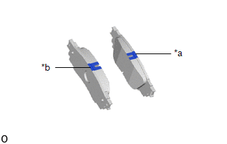
(a) Check the rear disc brake pad. HINT: If the rear disc brake pad has an identification mark, be sure to confirm the installation location. |
|
|
(b) Install 2 new rear disc brake pad wear indicator plates to each rear disc brake pad. NOTICE: Install the rear disc brake pad wear indicator plate in the correct positions and direction. |
|
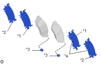
(c) Install the rear No. 1 disc brake anti-squeal shim and rear No. 2 disc brake anti-squeal shim to each rear disc brake pad.
NOTICE:
- Install the rear No. 1 disc brake anti-squeal shim and rear No. 2 disc brake anti-squeal shim in the correct positions and direction as shown in the illustration.
- Install the No. 1 disc brake anti-squeal shim and rear No. 2 disc brake anti squeal shim with the claws in the locations shown in the illustration to the outer side of the vehicle.
- Install so that the claws are towards the outer side of the vehicle.
2. INSTALL REAR DISC BRAKE PAD KIT
CAUTION:
- After lifting up the rear disc brake cylinder assembly, secure it in
place before performing any work on it.
.png)
- The rear disc brake cylinder assembly could fall, pinching hands or fingers and causing injury.
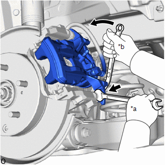
(a) Push back the rear disc brake piston.
NOTICE:
Do not forcibly install the rear disc brake piston into rear disc brake cylinder assembly.
(b) Install the 2 rear disc brake pads to the rear disc brake cylinder mounting.
NOTICE:
Make sure that disc brake grease is applied onto the lining surface of the rear disc brake pad.
|
(c) Hold the rear disc brake cylinder slide pin and install the rear disc brake cylinder assembly to the rear disc brake cylinder mounting with a new bolt. Torque: 34.3 N·m {350 kgf·cm, 25 ft·lbf} |
|
(d) Depress the brake pedal several times.
3. ADD BRAKE FLUID
Click here
.gif)
4. INSTALL REAR WHEEL
Click here
5. NORMAL CONDITION RECOVERY
Click here
 Removal
REMOVAL
CAUTION / NOTICE / HINT
HINT:
The following procedure is for the LH side.
Use the same procedure for the RH side and LH side.
PROCEDURE
1. PRECAUTION
Click here
2. ...

Other materials:
Toyota CH-R Service Manual > Air Conditioning System(for Automatic Air Conditioning System With Side-mounted
Air Conditioner Pressure Sensor): Precaution
PRECAUTION
IGNITION SWITCH EXPRESSIONS
(a) The type of ignition switch used on this model differs according to the specifications
of the vehicle. The expressions listed in the table below are used in this section.
Expression
Ignition Switch (Position)
Engine Swi ...
Toyota CH-R Service Manual > Continuously Variable Transaxle System: System Description
SYSTEM DESCRIPTION
SYSTEM DESCRIPTION
(a) The K114 (CVT) is a fully electrohydraulically controlled steel belt type
continuously variable transaxle. This is a highly efficient transaxle that is controlled
in conjunction with the engine, contributing to enhanced fuel efficiency and quietness
...
Toyota C-HR (AX20) 2023-2026 Owner's Manual
Toyota CH-R Owners Manual
- For safety and security
- Instrument cluster
- Operation of each component
- Driving
- Interior features
- Maintenance and care
- When trouble arises
- Vehicle specifications
- For owners
Toyota CH-R Service Manual
- Introduction
- Maintenance
- Audio / Video
- Cellular Communication
- Navigation / Multi Info Display
- Park Assist / Monitoring
- Brake (front)
- Brake (rear)
- Brake Control / Dynamic Control Systems
- Brake System (other)
- Parking Brake
- Axle And Differential
- Drive Shaft / Propeller Shaft
- K114 Cvt
- 3zr-fae Battery / Charging
- Networking
- Power Distribution
- Power Assist Systems
- Steering Column
- Steering Gear / Linkage
- Alignment / Handling Diagnosis
- Front Suspension
- Rear Suspension
- Tire / Wheel
- Tire Pressure Monitoring
- Door / Hatch
- Exterior Panels / Trim
- Horn
- Lighting (ext)
- Mirror (ext)
- Window / Glass
- Wiper / Washer
- Door Lock
- Heating / Air Conditioning
- Interior Panels / Trim
- Lighting (int)
- Meter / Gauge / Display
- Mirror (int)
- Power Outlets (int)
- Pre-collision
- Seat
- Seat Belt
- Supplemental Restraint Systems
- Theft Deterrent / Keyless Entry

0.0086