Toyota CH-R Service Manual: System Description
SYSTEM DESCRIPTION
GENERAL
(a) Acceleration sensors and pressure sensors used for the airbag system are installed to various parts on the vehicle and calculate the acceleration rate and pressure of each part during a collision.
(b) Depending on the situation, the airbag sensor assembly sends a deployment signal to SRS parts based on the information from each sensor.
DEPLOYMENT CONDITION
(a) FRONTAL COLLISION
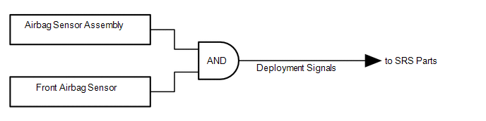
(1) Frontal collision signals are produced based on the information from the airbag sensor assembly and front airbag sensors.
HINT:
In the case of a frontal collision, the SRS deployment signal may be output after receiving an ON signal from the acceleration sensor built into the airbag sensor assembly even without a signal from the front airbag sensors.
(2) Frontal collision signals are used to deploy the SRS parts.
|
SRS Part |
Pretensioner Deployment Judgment |
Pretensioner and Airbag Deployment Judgment |
|||
|---|---|---|---|---|---|
|
LHD |
RHD |
LHD |
RHD |
||
|
Horn Button Assembly |
Driver Side Squib |
X |
X |
○ |
○ |
|
Driver Side Squib 2nd Step (w/ Occupant Classification System) |
X |
X |
○*2 |
○*2 |
|
|
Instrument Panel Passenger without Door Airbag Assembly |
Front Passenger Side Squib |
X |
X |
○*1 |
○*1 |
|
Front Passenger Side Squib 2nd Step (w/ Occupant Classification System) |
X |
X |
○*1 |
○*1 |
|
|
Lower No. 1 Instrument Panel Airbag Assembly |
X |
X |
○ |
○ |
|
|
Front Seat Cushion Airbag Assembly RH |
X |
X |
○*1 |
- |
|
|
Front Seat Airbag Assembly LH |
X |
X |
○ |
○ |
|
|
Front Seat Airbag Assembly RH |
X |
X |
○ |
○ |
|
|
Rear Seat Airbag Assembly LH (w/ Occupant Classification System) |
X |
X |
○ |
○ |
|
|
Rear Seat Airbag Assembly RH (w/ Occupant Classification System) |
X |
X |
○ |
○ |
|
|
Curtain Shield Airbag Assembly RH |
X |
X |
○ |
○ |
|
|
Curtain Shield Airbag Assembly LH |
X |
X |
○ |
○ |
|
|
Front Seat Outer Belt Assembly LH |
○ |
○ |
○ |
○ |
|
|
Front Seat Outer Belt Assembly RH |
Front Pretensioner Squib RH |
○*1 |
○ |
○*1 |
○ |
|
Selectable Force Limiter Squib RH |
○*1 |
- |
○*1 |
- |
|
|
Rear Seat 3 Point Type Outer Belt Assembly LH |
○ |
○ |
○ |
○ |
|
|
Rear Seat 3 Point Type Outer Belt Assembly RH |
○ |
○ |
○ |
○ |
|
- ○: Deployable
- X: Not Deployable
- *1: Deployment depends on airbag cut off switch cylinder sub-assembly condition.
- *2: Deployment depends on of driver seat belt condition and seat position.
- *3:*Deployment depends on front passenger seat condition.
(b) SIDE COLLISION (Pattern 1)
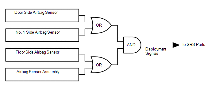
(1) Side collision (Pattern 1) signals are produced based on the information from the airbag sensor assembly, door side airbag sensor, No. 1 side airbag sensor and floor side airbag sensor.
(2) Side collision (Pattern 1) signals are used to deploy the SRS parts.
|
SRS Part |
Side Collision (Pattern 1) Detected |
||
|---|---|---|---|
|
LH Side Collision |
RH Side Collision |
||
|
Horn Button Assembly |
Driver Side Squib |
X |
X |
|
Driver Side Squib 2nd Step (w/ Occupant Classification System) |
X |
X |
|
|
Instrument Panel Passenger without Door Airbag Assembly |
Front Passenger Side Squib |
X |
X |
|
Front Passenger Side Squib 2nd Step (w/ Occupant Classification System) |
X |
X |
|
|
Lower No. 1 Instrument Panel Airbag Assembly |
X |
X |
|
|
Front Seat Cushion Airbag Assembly RH |
X |
X |
|
|
Front Seat Airbag Assembly LH |
○ |
X |
|
|
Front Seat Airbag Assembly RH |
X |
○ |
|
|
Rear Seat Airbag Assembly LH (w/ Occupant Classification System) |
○ |
X |
|
|
Rear Seat Airbag Assembly RH (w/ Occupant Classification System) |
X |
○ |
|
|
Curtain Shield Airbag Assembly RH |
○ |
X |
|
|
Curtain Shield Airbag Assembly LH |
X |
○ |
|
|
Front Seat Outer Belt Assembly LH |
○ |
X |
|
|
Front Seat Outer Belt Assembly RH |
Front Pretensioner Squib RH |
X |
X |
|
Selectable Force Limiter Squib RH |
X |
○ |
|
|
Rear Seat 3 Point Type Outer Belt Assembly LH (w/ Occupant Classification System) |
○ |
X |
|
|
Rear Seat 3 Point Type Outer Belt Assembly RH (w/ Occupant Classification System) |
X |
○ |
|
- ○: Deployable
- X: Not Deployable
(c) SIDE COLLISION (Pattern 2)
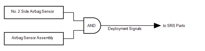
(1) Side collision (Pattern 2) signals are produced based on the information from the airbag sensor assembly and No. 2 side airbag sensor.
(2) Side collision (Pattern 2) signals are used to deploy the SRS parts.
|
SRS Part |
Side Collision (Pattern 2) Detected |
||
|---|---|---|---|
|
LH Side Collision |
RH Side Collision |
||
|
Horn Button Assembly |
Driver Side Squib |
X |
X |
|
Driver Side Squib 2nd Step (w/ Occupant Classification System) |
X |
X |
|
|
Instrument Panel Passenger without Door Airbag Assembly |
Front Passenger Side Squib |
X |
X |
|
Front Passenger Side Squib 2nd Step (w/ Occupant Classification System) |
X |
X |
|
|
Lower No. 1 Instrument Panel Airbag Assembly |
X |
X |
|
|
Front Seat Cushion Airbag Assembly RH |
X |
X |
|
|
Front Seat Airbag Assembly LH |
X |
X |
|
|
Front Seat Airbag Assembly RH |
X |
X |
|
|
Rear Seat Airbag Assembly LH (w/ Occupant Classification System) |
○ |
X |
|
|
Rear Seat Airbag Assembly RH (w/ Occupant Classification System) |
X |
○ |
|
|
Curtain Shield Airbag Assembly RH |
○ |
X |
|
|
Curtain Shield Airbag Assembly LH |
X |
○ |
|
|
Front Seat Outer Belt Assembly LH |
X |
X |
|
|
Front Seat Outer Belt Assembly RH |
Front Pretensioner Squib RH |
X |
X |
|
Selectable Force Limiter Squib RH |
X |
X |
|
|
Rear Seat 3 Point Type Outer Belt Assembly LH (w/ Occupant Classification System) |
○ |
X |
|
|
Rear Seat 3 Point Type Outer Belt Assembly RH (w/ Occupant Classification System) |
X |
○ |
|
- ○: Deployable
- X: Not Deployable
 System Diagram
SYSTEM DIAGRAM
Communication Table
Transmitting ECU
(Transmitter)
Receiving ECU
Signal
Communication Method
Airbag Sensor Assem ...
 How To Proceed With Troubleshooting
CAUTION / NOTICE / HINT
HINT:
Use the following procedure to troubleshoot the airbag system.
*: Use the Techstream.
PROCEDURE
1.
VEHICLE BROUGHT TO WORKSHO ...
Other materials:
Toyota CH-R Service Manual > Vehicle Stability Control System: Open in ABS Solenoid Relay Circuit (C146E)
DESCRIPTION
The ABS solenoid relay is built into the skid control ECU in the brake actuator
assembly. The ABS solenoid relay supplies power to the ABS and TRAC solenoids. The
skid control ECU detects a solenoid relay malfunction by performing a self check
and relay operation check.
...
Toyota CH-R Service Manual > Compressor(for Valeo Made): Components
COMPONENTS
ILLUSTRATION
*1
COMPRESSOR WITH PULLEY ASSEMBLY
*2
DISCHARGE HOSE SUB-ASSEMBLY
*3
NO. 1 ENGINE UNDER COVER
*4
SUCTION HOSE SUB-ASSEMBLY
*5
O-RING
-
...
Toyota C-HR (AX20) 2023-2026 Owner's Manual
Toyota CH-R Owners Manual
- For safety and security
- Instrument cluster
- Operation of each component
- Driving
- Interior features
- Maintenance and care
- When trouble arises
- Vehicle specifications
- For owners
Toyota CH-R Service Manual
- Introduction
- Maintenance
- Audio / Video
- Cellular Communication
- Navigation / Multi Info Display
- Park Assist / Monitoring
- Brake (front)
- Brake (rear)
- Brake Control / Dynamic Control Systems
- Brake System (other)
- Parking Brake
- Axle And Differential
- Drive Shaft / Propeller Shaft
- K114 Cvt
- 3zr-fae Battery / Charging
- Networking
- Power Distribution
- Power Assist Systems
- Steering Column
- Steering Gear / Linkage
- Alignment / Handling Diagnosis
- Front Suspension
- Rear Suspension
- Tire / Wheel
- Tire Pressure Monitoring
- Door / Hatch
- Exterior Panels / Trim
- Horn
- Lighting (ext)
- Mirror (ext)
- Window / Glass
- Wiper / Washer
- Door Lock
- Heating / Air Conditioning
- Interior Panels / Trim
- Lighting (int)
- Meter / Gauge / Display
- Mirror (int)
- Power Outlets (int)
- Pre-collision
- Seat
- Seat Belt
- Supplemental Restraint Systems
- Theft Deterrent / Keyless Entry

0.0086