Toyota CH-R Service Manual: Installation
INSTALLATION
PROCEDURE
1. INSTALL FRONT STABILIZER BAR BUSHING LH
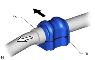
(a) Install the front stabilizer bar bushing LH to the front stabilizer bar as shown in the illustration.
|
*a |
Cutout |
|
*b |
Stopper |
.png) |
Front of the Vehicle |
.png) |
Outside of the Vehicle |
NOTICE:
- Install the front stabilizer bar bushing LH so that the cutout is facing the rear of the vehicle.
- Install the front stabilizer bar bushing LH onto the front stabilizer bar so that the stopper ring of the front stabilizer bar faces the outside of the vehicle.
2. INSTALL FRONT STABILIZER BAR BUSHING RH
HINT:
Perform the same procedure as for the LH side.
3. INSTALL FRONT STABILIZER BAR
(a) Install the front stabilizer bar with the 2 front stabilizer bar bushings to the front suspension crossmember sub-assembly.
NOTICE:
Make sure that the identification mark is positioned on the right side of the vehicle.
|
*a |
Identification Mark |
- |
- |
|
|
Front of the Vehicle |
- |
- |
4. INSTALL FRONT NO. 1 STABILIZER BRACKET LH
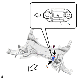
(a) Install the front No. 1 stabilizer bracket LH to the front suspension crossmember sub-assembly with the 2 bolts.
Torque:
103 N·m {1050 kgf·cm, 76 ft·lbf}
NOTICE:
- Make sure to install the front No. 1 stabilizer bracket LH with its arrow facing the front of the vehicle.
- Temporarily tighten the bolt (B) and then fully tighten the 2 bolts in the order of (A) and (B).
|
*a |
Arrow |
|
|
Front of the Vehicle |
5. INSTALL FRONT NO. 1 STABILIZER BRACKET RH
HINT:
Perform the same procedure as for the LH side.
6. INSTALL FRONT STABILIZER LINK ASSEMBLY LH
(a) Install the front stabilizer link assembly LH to the front stabilizer bar LH with the nut.
Torque:
74 N·m {755 kgf·cm, 55 ft·lbf}
HINT:
If the ball joint turns together with the nut, use a 6 mm hexagon socket wrench to hold the stud bolt.
7. INSTALL FRONT STABILIZER LINK ASSEMBLY RH
HINT:
Perform the same procedure as for the LH side.
8. INSTALL STEERING LINK ASSEMBLY
(a) Install the steering link assembly to the front suspension crossmember sub-assembly with the 2 bolts and 2 new nuts.
Torque:
133 N·m {1356 kgf·cm, 98 ft·lbf}
NOTICE:
- Because the nut has its own stopper, do not turn the nut. Tighten the bolt with the nut secured.
- Make sure to tighten the bolts starting from the left side of the vehicle.
9. INSTALL FRONT SUSPENSION CROSSMEMBER SUB-ASSEMBLY
Click here
.gif)
 Inspection
INSPECTION
PROCEDURE
1. INSPECT FRONT STABILIZER LINK ASSEMBLY
(a) Inspect the turning torque of the ball joint.
(1) Secure the front stabilizer link assembly in a vise using aluminum ...

Other materials:
Toyota CH-R Owners Manual > Using the interior lights: Interior lights
■ Front Turns the door position on/off
■ Rear
On
Door position
Operation is linked with the front interior light main switch. When the switch
is off, the light does not illuminate.
Off
...
Toyota CH-R Owners Manual > Child restraint systems: Child restraint system fixed with a child restraint LATCH anchor
■ Child restraint LATCH anchors LATCH anchors are provided for
the rear outboard seats.
(Buttons displaying the location of the anchors are attached to the seats.)
■ When installing in the rear outboard seats Install the child
restraint system in accordance to the operation manual encl ...
Toyota C-HR (AX20) 2023-2026 Owner's Manual
Toyota CH-R Owners Manual
- For safety and security
- Instrument cluster
- Operation of each component
- Driving
- Interior features
- Maintenance and care
- When trouble arises
- Vehicle specifications
- For owners
Toyota CH-R Service Manual
- Introduction
- Maintenance
- Audio / Video
- Cellular Communication
- Navigation / Multi Info Display
- Park Assist / Monitoring
- Brake (front)
- Brake (rear)
- Brake Control / Dynamic Control Systems
- Brake System (other)
- Parking Brake
- Axle And Differential
- Drive Shaft / Propeller Shaft
- K114 Cvt
- 3zr-fae Battery / Charging
- Networking
- Power Distribution
- Power Assist Systems
- Steering Column
- Steering Gear / Linkage
- Alignment / Handling Diagnosis
- Front Suspension
- Rear Suspension
- Tire / Wheel
- Tire Pressure Monitoring
- Door / Hatch
- Exterior Panels / Trim
- Horn
- Lighting (ext)
- Mirror (ext)
- Window / Glass
- Wiper / Washer
- Door Lock
- Heating / Air Conditioning
- Interior Panels / Trim
- Lighting (int)
- Meter / Gauge / Display
- Mirror (int)
- Power Outlets (int)
- Pre-collision
- Seat
- Seat Belt
- Supplemental Restraint Systems
- Theft Deterrent / Keyless Entry

0.0131