Toyota CH-R Service Manual: IG Power Supply Voltage (C1551)
DESCRIPTION
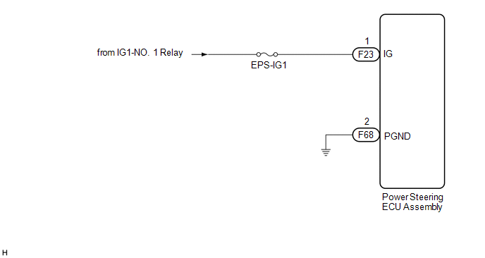
The power steering ECU assembly distinguishes the ignition switch status as ON or off through the IG power source circuit.
|
DTC No. |
Detection Item |
DTC Detection Condition |
Trouble Area |
Warning Indicate |
Return-to-normal Condition |
Note |
|---|---|---|---|---|---|---|
|
C1551 |
IG Power Supply Voltage |
Open or short in IG power source circuit with power switch on (IG) |
|
EPS warning light: Comes on |
The ECU judges the system has returned to normal or the ignition switch is turned ON again |
- |
WIRING DIAGRAM
CAUTION / NOTICE / HINT
NOTICE:
- If the power steering ECU assembly has been replaced, perform assist
map writing and torque sensor zero point calibration.
Click here
.gif)
- Inspect the fuses for circuits related to this system before performing the following procedure.
PROCEDURE
|
1. |
CHECK HARNESS AND CONNECTOR (BATTERY - POWER STEERING ECU ASSEMBLY) |
|
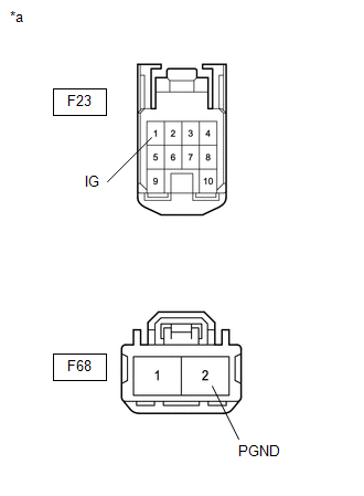
(a) Disconnect the F68 and F23 power steering ECU assembly connectors. |
|
(b) Measure the voltage according to the value(s) in the table below.
Standard Voltage:
|
Tester Connection |
Condition |
Specified Condition |
|---|---|---|
|
F23-1 (IG) - Body ground |
Ignition switch ON |
8 to 16 V |
(c) Measure the resistance according to the value(s) in the table below.
Standard Resistance:
|
Tester Connection |
Condition |
Specified Condition |
|---|---|---|
|
F68-2 (PGND) - Body ground |
Always |
Below 1 Ω |
| OK | .gif) |
REPLACE POWER STEERING ECU ASSEMBLY |
| NG | |
REPAIR OR REPLACE HARNESS OR CONNECTOR |
 Assist Map Number Un-Writing (C1581)
DESCRIPTION
This DTC will be stored if the power steering ECU assembly determines that the
assist map is not written in the ECU.
DTC No.
Detection Item
DTC Detecti ...
 Error in Matching of ECUs (C1567)
DESCRIPTION
Based on the steering sensor signal, the power steering ECU assembly determines
if the correct type of steering sensor is installed.
DTC No.
Detection Item
...
Other materials:
Toyota CH-R Service Manual > Combination Meter: Components
COMPONENTS
ILLUSTRATION
*1
COMBINATION METER ASSEMBLY
*2
INSTRUMENT CLUSTER FINISH PANEL ASSEMBLY
*3
INSTRUMENT CLUSTER FINISH PANEL GARNISH ASSEMBLY
*4
INSTRUMENT CLUSTER FINISH PANEL SUB-ASSEMBLY
...
Toyota CH-R Service Manual > Front Bumper: Installation
INSTALLATION
PROCEDURE
1. INSTALL FRONT BUMPER ASSEMBLY
(a) Move the front bumper assembly into position.
(b) w/ Toyota Safety Sense:
(1) Connect the connector.
(c) Temporarily install the front bumper assembly with the claw as shown in the
illustration.
Install in thi ...
Toyota C-HR (AX20) 2023-2026 Owner's Manual
Toyota CH-R Owners Manual
- For safety and security
- Instrument cluster
- Operation of each component
- Driving
- Interior features
- Maintenance and care
- When trouble arises
- Vehicle specifications
- For owners
Toyota CH-R Service Manual
- Introduction
- Maintenance
- Audio / Video
- Cellular Communication
- Navigation / Multi Info Display
- Park Assist / Monitoring
- Brake (front)
- Brake (rear)
- Brake Control / Dynamic Control Systems
- Brake System (other)
- Parking Brake
- Axle And Differential
- Drive Shaft / Propeller Shaft
- K114 Cvt
- 3zr-fae Battery / Charging
- Networking
- Power Distribution
- Power Assist Systems
- Steering Column
- Steering Gear / Linkage
- Alignment / Handling Diagnosis
- Front Suspension
- Rear Suspension
- Tire / Wheel
- Tire Pressure Monitoring
- Door / Hatch
- Exterior Panels / Trim
- Horn
- Lighting (ext)
- Mirror (ext)
- Window / Glass
- Wiper / Washer
- Door Lock
- Heating / Air Conditioning
- Interior Panels / Trim
- Lighting (int)
- Meter / Gauge / Display
- Mirror (int)
- Power Outlets (int)
- Pre-collision
- Seat
- Seat Belt
- Supplemental Restraint Systems
- Theft Deterrent / Keyless Entry

0.0136