Toyota CH-R Service Manual: Terminals Of Ecu
TERMINALS OF ECU
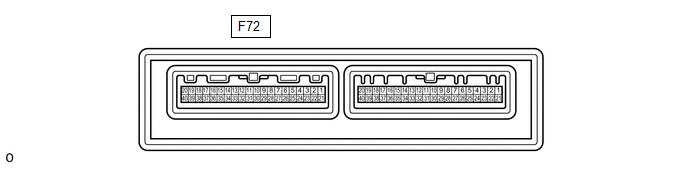
CHECK AIR CONDITIONING AMPLIFIER ASSEMBLY (for TMMT Made)
(a) Disconnect the F72 air conditioning amplifier assembly connector.
(b) Measure the voltage and resistance according to the value(s) in the table below.
|
Tester Connection |
Wiring Color |
Terminal Description |
Condition |
Specified Condition |
|---|---|---|---|---|
|
F72-5 (IG+) - Body ground |
B - Body ground |
Power source (IG) |
Ignition switch ON |
11 to 14 V |
|
Ignition switch off |
Below 1 V |
|||
|
F72-1 (B) - Body ground |
V - Body ground |
Battery power supply |
Always |
11 to 14 V |
|
F72-29 (GND) - Body ground |
W-B - Body ground |
Ground |
Always |
Below 1 Ω |
(c) Reconnect the F72 air conditioning amplifier assembly connector.
(d) Measure the voltage according to the value(s) in the table below.
|
Tester Connection |
Wiring Color |
Terminal Description |
Condition |
Specified Condition |
|---|---|---|---|---|
|
F72-24 (FDEF) - Body ground |
W - Body ground |
Wiper deicer signal |
Ignition switch ON, windshield deicer switch on |
Below 1 V |
|
Ignition switch ON, windshield deicer switch off |
11 to 14 V |
|||
|
F72-3 (LIN1) - Body ground |
L - Body ground |
LIN communication line |
Ignition switch ON |
Pulse generation |
.png)
CHECK AIR CONDITIONING AMPLIFIER ASSEMBLY (for TMC Made)
(a) Disconnect the F139 air conditioning amplifier assembly connector.
(b) Measure the voltage and resistance according to the value(s) in the table below.
|
Tester Connection |
Wiring Color |
Terminal Description |
Condition |
Specified Condition |
|---|---|---|---|---|
|
F139-2 (IG+) - Body ground |
B - Body ground |
Power source (IG) |
Ignition switch ON |
11 to 14 V |
|
Ignition switch off |
Below 1 V |
|||
|
F139-1 (B) - Body ground |
V - Body ground |
Battery power supply |
Always |
11 to 14 V |
|
F139-4 (GND) - Body ground |
W-B - Body ground |
Ground |
Always |
Below 1 Ω |
(c) Reconnect the F139 air conditioning amplifier assembly connector.
(d) Measure the voltage according to the value(s) in the table below.
|
Tester Connection |
Wiring Color |
Terminal Description |
Condition |
Specified Condition |
|---|---|---|---|---|
|
F139-17 (FDEF) - Body ground |
W - Body ground |
Wiper deicer signal |
Ignition switch ON, windshield deicer switch on |
Below 1 V |
|
Ignition switch ON, windshield deicer switch off |
11 to 14 V |
|||
|
F139-14 (LIN1) - Body ground |
BE - Body ground |
LIN communication line |
Ignition switch ON |
Pulse generation |
CHECK AIR CONDITIONING CONTROL ASSEMBLY

(a) Check for pulse according to the value(s) in the table below.
|
Terminal No. (Symbol) |
Wiring Color |
Terminal Description |
Condition |
Specified Condition |
|---|---|---|---|---|
|
F61-2 (LIN1) - F61-16 (GND) |
L - W-B*1 BE - W-B*2 |
LIN communication line |
Ignition switch ON |
Pulse generation |
- *1: for TMMT Made
- *2: for TMC Made
 Problem Symptoms Table
PROBLEM SYMPTOMS TABLE
NOTICE:
If the battery voltage becomes low, windshield deicer operation is canceled to
prioritize supplying power to the power steering system.
Click here
HINT:
...
 Data List / Active Test
DATA LIST / ACTIVE TEST
ACTIVE TEST
HINT:
Using the Techstream to perform Active Tests allows relays, VSVs, actuators and
other items to be operated without removing any parts. This non-intrusive ...
Other materials:
Toyota CH-R Service Manual > Power Window Control System: Initialization
INITIALIZATION
INITIALIZE POWER WINDOW CONTROL SYSTEM (ALL DOORS)
NOTICE:
When a door window regulator sub-assembly, power window regulator motor
assembly, door glass or door glass run is reinstalled or replaced, the power
window control system must be initialized. Functions such ...
Toyota CH-R Service Manual > Front Suspension Member: Components
COMPONENTS
ILLUSTRATION
*1
NO. 1 ENGINE UNDER COVER
*2
REAR ENGINE UNDER COVER LH
*3
REAR ENGINE UNDER COVER RH
-
-
N*m (kgf*cm, ft.*lbf): Specified torque
-
...
Toyota C-HR (AX20) 2023-2026 Owner's Manual
Toyota CH-R Owners Manual
- For safety and security
- Instrument cluster
- Operation of each component
- Driving
- Interior features
- Maintenance and care
- When trouble arises
- Vehicle specifications
- For owners
Toyota CH-R Service Manual
- Introduction
- Maintenance
- Audio / Video
- Cellular Communication
- Navigation / Multi Info Display
- Park Assist / Monitoring
- Brake (front)
- Brake (rear)
- Brake Control / Dynamic Control Systems
- Brake System (other)
- Parking Brake
- Axle And Differential
- Drive Shaft / Propeller Shaft
- K114 Cvt
- 3zr-fae Battery / Charging
- Networking
- Power Distribution
- Power Assist Systems
- Steering Column
- Steering Gear / Linkage
- Alignment / Handling Diagnosis
- Front Suspension
- Rear Suspension
- Tire / Wheel
- Tire Pressure Monitoring
- Door / Hatch
- Exterior Panels / Trim
- Horn
- Lighting (ext)
- Mirror (ext)
- Window / Glass
- Wiper / Washer
- Door Lock
- Heating / Air Conditioning
- Interior Panels / Trim
- Lighting (int)
- Meter / Gauge / Display
- Mirror (int)
- Power Outlets (int)
- Pre-collision
- Seat
- Seat Belt
- Supplemental Restraint Systems
- Theft Deterrent / Keyless Entry

0.0133