Toyota CH-R Service Manual: Torque Sensor1 (C1511-C1514,C1517)
DESCRIPTION
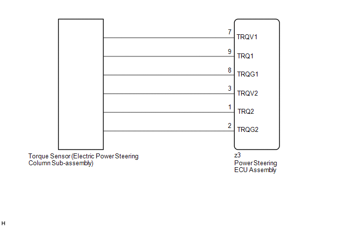
The torque sensor converts the rotational torque received from the steering wheel into electric signals and sends them to the power steering ECU assembly.
|
DTC No. |
Detection Item |
DTC Detection Condition |
Trouble Area |
Warning Indicate |
Return-to-normal Condition |
Note |
|---|---|---|---|---|---|---|
|
C1511 |
Torque Sensor1 |
Torque sensor malfunction |
|
EPS warning light: Comes on |
The ECU judges the system has returned to normal or the ignition switch ON again |
- |
|
C1512 |
Torque Sensor2 |
Torque sensor malfunction |
|
EPS warning light: Comes on |
The ECU judges the system has returned to normal or the ignition switch ON again |
- |
|
C1513 |
Torque Sensor Deviation Excessive |
Torque sensor malfunction |
|
EPS warning light: Comes on |
The ECU judges the system has returned to normal or the ignition switch ON again |
- |
|
C1514 |
Torque Sensor Power Supply Voltage |
Torque sensor malfunction |
|
EPS warning light: Comes on |
Ignition switch ON again |
- |
|
C1517 |
Torque Hold |
Torque sensor malfunction |
|
EPS warning light: Comes on |
Ignition switch ON again |
- |
WIRING DIAGRAM
CAUTION / NOTICE / HINT
NOTICE:
- If the electric power steering column sub-assembly has been replaced,
perform torque sensor zero point calibration.
Click here
.gif)
- If the power steering ECU assembly has been replaced, perform assist
map writing and torque sensor zero point calibration.
Click here
PROCEDURE
|
1. |
CHECK CONNECTOR CONNECTION CONDITION |
(a) Check the connection condition of the torque sensor connector.
OK:
Torque sensor connector is securely connected to the power steering ECU assembly.
| NG | .gif) |
CONNECT CONNECTOR |
|
.gif)
|
2. |
CHECK POWER STEERING ECU ASSEMBLY (TRQV VOLTAGE) |
|
(a) Turn the ignition switch to ON. |
|
(b) Measure the voltage according to the value(s) in the table below.
Standard Voltage:
|
Tester Connection |
Condition |
Specified Condition |
|---|---|---|
|
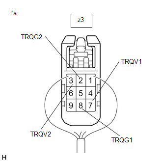
z3-7 (TRQV1) - z3-8 (TRQG1) |
Ignition switch ON |
4.5 to 5.5 V |
|
z3-3 (TRQV2) - z3-2 (TRQG2) |
Ignition switch ON |
4.5 to 5.5 V |
| NG | |
REPLACE POWER STEERING ECU ASSEMBLY |
|
|
3. |
CHECK POWER STEERING ECU ASSEMBLY (TRQ1, TRQ2 VOLTAGE) |
|
(a) Turn the engine running. |
|
(b) Measure the voltage according to the value(s) in the table below.
Standard Voltage:
|
Tester Connection |
Condition |
Specified Condition |
|---|---|---|
|
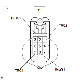
z3-9 (TRQ1) - z3-8 (TRQG1) |
Engine running and steering wheel not being turned (without load) |
2.3 to 2.7 V |
|
Engine running and steering wheel being turned to the right with vehicle stopped |
2.5 to 3.8 V |
|
|
Engine running and steering wheel being turned to the left with vehicle stopped |
1.2 to 2.5 V |
|
|
z3-1 (TRQ2) - z3-2 (TRQG2) |
Engine running and steering wheel not being turned (without load) |
2.3 to 2.7 V |
|
Engine running and steering wheel being turned to the right with vehicle stopped |
1.2 to 2.5 V |
|
|
Engine running and steering wheel being turned to the left with vehicle stopped |
2.5 to 3.8 V |
(c) Under each condition, measure the voltage at terminals TRQ1 and TRQ2, and calculate the sum.
Standard Voltage:
|
Tester Connection |
Condition |
Specified Condition |
|---|---|---|
|
Sum of voltage between z3-9 (TRQ1) and z3-8 (TRQG1) and voltage between z3-1 (TRQ2) and z3-2 (TRQG2) |
Engine running and steering wheel not being turned (without load) |
Between 4.75 V and 5.25 V |
|
Engine running and steering wheel being turned to the right with vehicle stopped |
||
|
Engine running and steering wheel being turned to the left with vehicle stopped |
| OK | |
REPLACE POWER STEERING ECU ASSEMBLY |
| NG | |
REPLACE ELECTRIC POWER STEERING COLUMN SUB-ASSEMBLY |
 PIG Power Supply Voltage (C1552,C1554)
DESCRIPTION
If a problem occurs in the system, the power source relay circuit and the motor
relay circuit are shut off to stop power assist. The ECU must be replaced when there
is a problem with ...
 Torque Sensor Zero Point Adjustment Undone (C1515)
DESCRIPTION
This DTC does not indicate a malfunction. The power steering ECU assembly stores
this DTC when it determines that torque sensor zero point calibration has not been
performed.
...
Other materials:
Toyota CH-R Service Manual > Safety Connect System: Diagnostic Trouble Code Chart
DIAGNOSTIC TROUBLE CODE CHART
Safety Connect System
DTC No.
Detection Item
Link
B1536
Short in Telephone SUB Antenna Circuit
B1537
Open in Telephone SUB Antenna Circuit
...
Toyota CH-R Service Manual > Front Evaporator Temperature Sensor(for Denso Made): Inspection
INSPECTION
PROCEDURE
1. INSPECT NO. 1 COOLER THERMISTOR
(a) Check the resistance.
(1) Measure the resistance according to the value(s) in the table below.
*a
Component without harness connected
(No. 1 Cooler Thermistor)
*b
Sensing Portion
...
Toyota C-HR (AX20) 2023-2026 Owner's Manual
Toyota CH-R Owners Manual
- For safety and security
- Instrument cluster
- Operation of each component
- Driving
- Interior features
- Maintenance and care
- When trouble arises
- Vehicle specifications
- For owners
Toyota CH-R Service Manual
- Introduction
- Maintenance
- Audio / Video
- Cellular Communication
- Navigation / Multi Info Display
- Park Assist / Monitoring
- Brake (front)
- Brake (rear)
- Brake Control / Dynamic Control Systems
- Brake System (other)
- Parking Brake
- Axle And Differential
- Drive Shaft / Propeller Shaft
- K114 Cvt
- 3zr-fae Battery / Charging
- Networking
- Power Distribution
- Power Assist Systems
- Steering Column
- Steering Gear / Linkage
- Alignment / Handling Diagnosis
- Front Suspension
- Rear Suspension
- Tire / Wheel
- Tire Pressure Monitoring
- Door / Hatch
- Exterior Panels / Trim
- Horn
- Lighting (ext)
- Mirror (ext)
- Window / Glass
- Wiper / Washer
- Door Lock
- Heating / Air Conditioning
- Interior Panels / Trim
- Lighting (int)
- Meter / Gauge / Display
- Mirror (int)
- Power Outlets (int)
- Pre-collision
- Seat
- Seat Belt
- Supplemental Restraint Systems
- Theft Deterrent / Keyless Entry

0.0078