Toyota CH-R Service Manual: PIG Power Supply Voltage (C1552,C1554)
DESCRIPTION
If a problem occurs in the system, the power source relay circuit and the motor relay circuit are shut off to stop power assist. The ECU must be replaced when there is a problem with the relays because the relays are built into the ECU.
|
DTC No. |
Detection Item |
DTC Detection Condition |
Trouble Area |
Warning Indicate |
Return-to-normal Condition |
Note |
|---|---|---|---|---|---|---|
|
C1552 |
PIG Power Supply Voltage |
PIG power source circuit malfunction |
|
EPS warning light: Comes on |
Ignition switch ON again |
- |
|
C1554 |
Power Supply Relay Failure |
Power source relay circuit malfunction |
|
EPS warning light: Comes on |
Ignition switch ON again |
- |
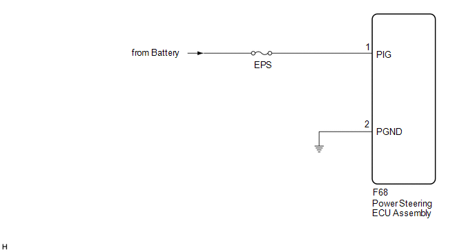
WIRING DIAGRAM
CAUTION / NOTICE / HINT
NOTICE:
- If the power steering ECU assembly has been replaced, perform assist
map writing and torque sensor zero point calibration.
Click here
.gif)
- Inspect the fuses for circuits related to this system before performing the following procedure.
PROCEDURE
|
1. |
CHECK HARNESS AND CONNECTOR (POWER STEERING ECU ASSEMBLY - BODY GROUND) |
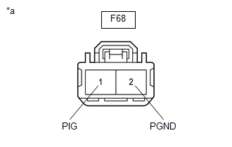
(a) Disconnect the F68 power steering ECU assembly connectors.
(b) Measure the voltage according to the value(s) in the table below.
Standard Voltage:
|
Tester Connection |
Condition |
Specified Condition |
|---|---|---|
|
F68-1 (PIG) - Body ground |
Ignition switch ON |
9 to 16 V |
|
(c) Measure the resistance according to the value(s) in the table below. Standard Resistance:
|
|
| OK | .gif) |
REPLACE POWER STEERING ECU ASSEMBLY |
| NG | |
REPAIR OR REPLACE HARNESS OR CONNECTOR |
 Assist Map Number Mismatch (C1582)
DESCRIPTION
When an incorrect ECM, main body ECU (multiplex network body ECU) or skid control
ECU (brake actuator assembly) is installed after the assist map has been written
to the power steerin ...
 Torque Sensor1 (C1511-C1514,C1517)
DESCRIPTION
The torque sensor converts the rotational torque received from the steering wheel
into electric signals and sends them to the power steering ECU assembly.
DTC No.
...
Other materials:
Toyota CH-R Service Manual > Rear Disc Brake Pad(for Tmc Made): Components
COMPONENTS
ILLUSTRATION
*1
REAR DISC BRAKE CYLINDER ASSEMBLY
*2
REAR NO. 2 DISC BRAKE ANTI-SQUEAL SHIM
*3
REAR NO. 1 DISC BRAKE ANTI-SQUEAL SHIM
*4
REAR DISC BRAKE ANTI-SQUEAL SHIM KIT
...
Toyota CH-R Service Manual > Rear Door Speaker: Installation
INSTALLATION
CAUTION / NOTICE / HINT
HINT:
Use the same procedure for the RH and LH sides.
The procedure listed below is for the LH side.
PROCEDURE
1. INSTALL REAR SPEAKER ASSEMBLY
(a) Engage the claw and guide to temporarily install the rear speaker
assembly.
...
Toyota C-HR (AX20) 2023-2026 Owner's Manual
Toyota CH-R Owners Manual
- For safety and security
- Instrument cluster
- Operation of each component
- Driving
- Interior features
- Maintenance and care
- When trouble arises
- Vehicle specifications
- For owners
Toyota CH-R Service Manual
- Introduction
- Maintenance
- Audio / Video
- Cellular Communication
- Navigation / Multi Info Display
- Park Assist / Monitoring
- Brake (front)
- Brake (rear)
- Brake Control / Dynamic Control Systems
- Brake System (other)
- Parking Brake
- Axle And Differential
- Drive Shaft / Propeller Shaft
- K114 Cvt
- 3zr-fae Battery / Charging
- Networking
- Power Distribution
- Power Assist Systems
- Steering Column
- Steering Gear / Linkage
- Alignment / Handling Diagnosis
- Front Suspension
- Rear Suspension
- Tire / Wheel
- Tire Pressure Monitoring
- Door / Hatch
- Exterior Panels / Trim
- Horn
- Lighting (ext)
- Mirror (ext)
- Window / Glass
- Wiper / Washer
- Door Lock
- Heating / Air Conditioning
- Interior Panels / Trim
- Lighting (int)
- Meter / Gauge / Display
- Mirror (int)
- Power Outlets (int)
- Pre-collision
- Seat
- Seat Belt
- Supplemental Restraint Systems
- Theft Deterrent / Keyless Entry

0.0127