Toyota CH-R Service Manual: Unlock Warning Switch
Components
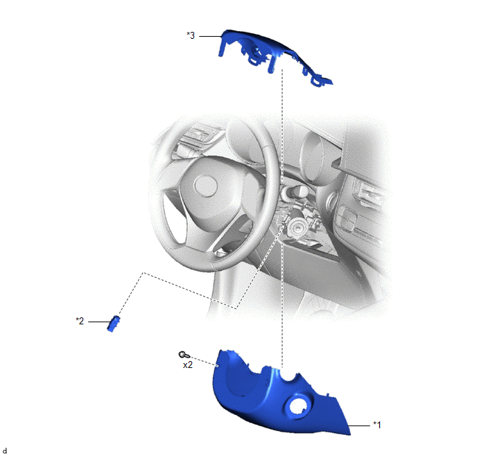
COMPONENTS
ILLUSTRATION
|
*1 |
LOWER STEERING COLUMN COVER |
*2 |
UNLOCK WARNING SWITCH ASSEMBLY |
|
*3 |
UPPER STEERING COLUMN COVER |
- |
- |
Inspection
INSPECTION
PROCEDURE
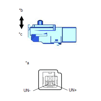
1. INSPECT UNLOCK WARNING SWITCH ASSEMBLY
|
(a) Check the resistance. (1) Measure the resistance according to the value(s) in the table below. Standard Resistance:
If the result is not as specified, replace the unlock warning switch assembly. |
|
Removal
REMOVAL
PROCEDURE
1. REMOVE LOWER STEERING COLUMN COVER
Click here
.gif)
2. REMOVE UPPER STEERING COLUMN COVER
Click here
3. REMOVE UNLOCK WARNING SWITCH ASSEMBLY
|
(a) Insert the key into the ignition key cylinder. |
|
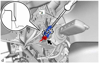
(b) Disconnect the connector.
(c) Using a screwdriver with its tip wrapped in protective tape, disengage the claws to remove the unlock warning switch assembly.
Installation
INSTALLATION
PROCEDURE
1. INSTALL UNLOCK WARNING SWITCH ASSEMBLY
|
(a) Engage the claws to install the unlock warning switch assembly. |
|
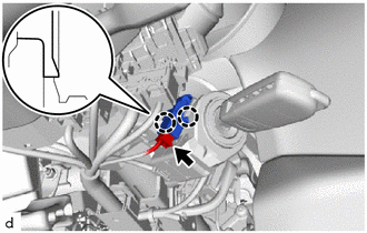
(b) Connect the connector.
(c) Remove the key from the ignition key cylinder.
2. INSTALL UPPER STEERING COLUMN COVER
Click here
.gif)
3. INSTALL LOWER STEERING COLUMN COVER
Click here
 Transmitter Battery(w/o Smart Key System)
Components
COMPONENTS
ILLUSTRATION
*1
TRANSMITTER BATTERY
*2
TRANSMITTER HOUSING COVER
*3
DOOR CONTROL TRANSMITTER PACKIN ...
 Wireless Door Lock Buzzer
Components
COMPONENTS
ILLUSTRATION
*1
WIRELESS DOOR LOCK BUZZER
-
-
Removal
REMOVAL
PROCEDURE
1. SEPARATE FRONT FENDER LINER LH
Click ...
Other materials:
Toyota CH-R Service Manual > Audio And Visual System(for Radio Receiver Type): Noise Occurs
PROCEDURE
1.
NOISE CONDITION
(a) Check from which direction the noise comes (front left or right, rear left
or right).
OK:
The location of the noise source can be determined.
NG
GO TO STEP 3
OK
...
Toyota CH-R Service Manual > Front Drive Shaft Assembly: Installation
INSTALLATION
CAUTION / NOTICE / HINT
HINT:
Use the same procedure for the RH side and LH side.
The following procedure is for the LH side.
PROCEDURE
1. INSTALL FRONT DRIVE INBOARD JOINT HOLE SNAP RING LH (for LH Side)
(a) Install a new front drive inboard joint hole snap ring ...
Toyota C-HR (AX20) 2023-2026 Owner's Manual
Toyota CH-R Owners Manual
- For safety and security
- Instrument cluster
- Operation of each component
- Driving
- Interior features
- Maintenance and care
- When trouble arises
- Vehicle specifications
- For owners
Toyota CH-R Service Manual
- Introduction
- Maintenance
- Audio / Video
- Cellular Communication
- Navigation / Multi Info Display
- Park Assist / Monitoring
- Brake (front)
- Brake (rear)
- Brake Control / Dynamic Control Systems
- Brake System (other)
- Parking Brake
- Axle And Differential
- Drive Shaft / Propeller Shaft
- K114 Cvt
- 3zr-fae Battery / Charging
- Networking
- Power Distribution
- Power Assist Systems
- Steering Column
- Steering Gear / Linkage
- Alignment / Handling Diagnosis
- Front Suspension
- Rear Suspension
- Tire / Wheel
- Tire Pressure Monitoring
- Door / Hatch
- Exterior Panels / Trim
- Horn
- Lighting (ext)
- Mirror (ext)
- Window / Glass
- Wiper / Washer
- Door Lock
- Heating / Air Conditioning
- Interior Panels / Trim
- Lighting (int)
- Meter / Gauge / Display
- Mirror (int)
- Power Outlets (int)
- Pre-collision
- Seat
- Seat Belt
- Supplemental Restraint Systems
- Theft Deterrent / Keyless Entry

0.0104