Toyota CH-R Service Manual: Parts Location
PARTS LOCATION
ILLUSTRATION
|
*A |
w/ Double Locking System |
- |
- |
|
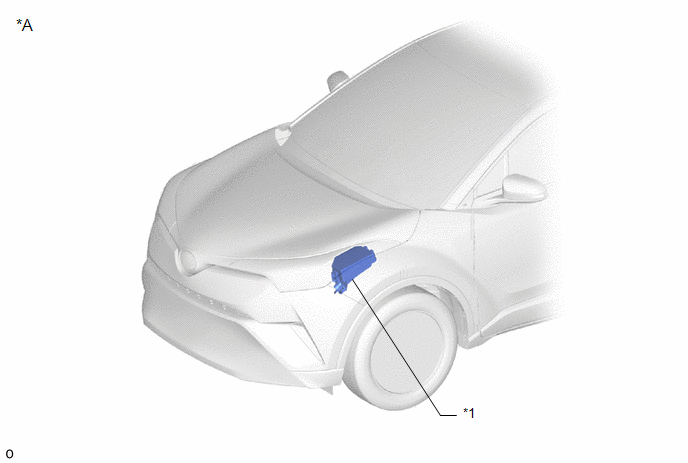
*1 |
NO. 1 ENGINE ROOM RELAY BLOCK - DOOR DBL/L FUSE |
- |
- |
ILLUSTRATION
|
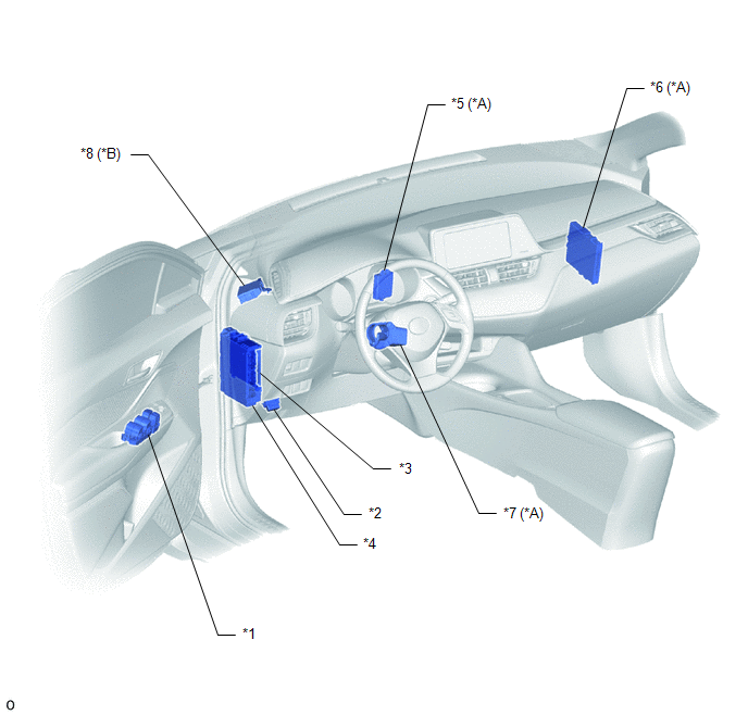
*A |
w/ Smart Key System |
*B |
w/ Double Locking System |
|
*1 |
MULTIPLEX NETWORK MASTER SWITCH ASSEMBLY |
*2 |
DLC3 |
|
*3 |
MAIN BODY ECU (MULTIPLEX NETWORK BODY ECU) |
*4 |
INSTRUMENT PANEL JUNCTION BLOCK ASSEMBLY - ECU-B NO. 1 FUSE - ECU-B NO. 2 FUSE - POWER FUSE - DOOR FUSE - DOOR R/L FUSE - DOOR R/R FUSE - AM2 FUSE - STRG LOCK FUSE - ECU-DCC NO. 2 FUSE |
|
*5 |
ID CODE BOX (IMMOBILISER CODE ECU) |
*6 |
CERTIFICATION ECU (SMART KEY ECU ASSEMBLY) |
|
*7 |
STEERING LOCK ECU (STEERING LOCK ACTUATOR OR UPPER BRACKET ASSEMBLY) |
*8 |
DOUBLE LOCK DOOR CONTROL RELAY ASSEMBLY |
ILLUSTRATION
|
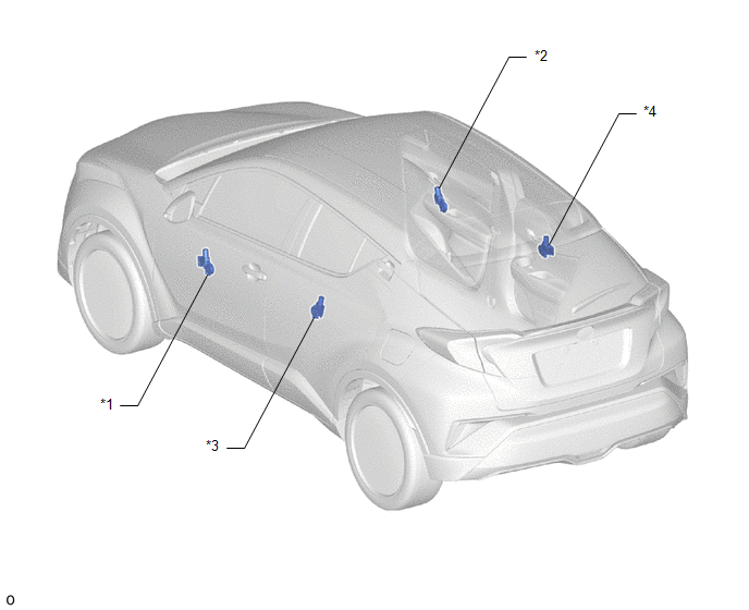
*1 |
POWER WINDOW REGULATOR MOTOR ASSEMBLY (for Driver Door) |
*2 |
POWER WINDOW REGULATOR MOTOR ASSEMBLY (for Front Passenger Door) |
|
*3 |
POWER WINDOW REGULATOR MOTOR ASSEMBLY (for Rear LH Door) |
*4 |
POWER WINDOW REGULATOR MOTOR ASSEMBLY (for Rear RH Door) |
 Precaution
PRECAUTION
IGNITION SWITCH EXPRESSIONS
(a) The type of ignition switch used on this model differs depending on the specifications
of the vehicle. The expressions listed in the table below are used ...
 System Diagram
SYSTEM DIAGRAM
DOOR BUS LINES
CERTIFICATION BUS LINES (w/ Smart Key System)
...
Other materials:
Toyota CH-R Service Manual > Navigation System: Black Screen
PROCEDURE
1.
CHECK DISPLAY SETTING
(a) Check that the display is not in screen off mode.
OK:
The display setting is not in screen off mode.
NG
CHANGE SCREEN TO SCREEN ON MODE
OK
...
Toyota CH-R Service Manual > Quarter Garnish: Installation
INSTALLATION
CAUTION / NOTICE / HINT
HINT:
Use the same procedure for the RH side and LH side.
The following procedure is for the LH side.
PROCEDURE
1. INSTALL QUARTER PILLAR COVER SUB-ASSEMBLY
HINT:
When installing a new quarter pillar cover sub-assembly, heat the vehicle b ...
Toyota C-HR (AX20) 2023-2026 Owner's Manual
Toyota CH-R Owners Manual
- For safety and security
- Instrument cluster
- Operation of each component
- Driving
- Interior features
- Maintenance and care
- When trouble arises
- Vehicle specifications
- For owners
Toyota CH-R Service Manual
- Introduction
- Maintenance
- Audio / Video
- Cellular Communication
- Navigation / Multi Info Display
- Park Assist / Monitoring
- Brake (front)
- Brake (rear)
- Brake Control / Dynamic Control Systems
- Brake System (other)
- Parking Brake
- Axle And Differential
- Drive Shaft / Propeller Shaft
- K114 Cvt
- 3zr-fae Battery / Charging
- Networking
- Power Distribution
- Power Assist Systems
- Steering Column
- Steering Gear / Linkage
- Alignment / Handling Diagnosis
- Front Suspension
- Rear Suspension
- Tire / Wheel
- Tire Pressure Monitoring
- Door / Hatch
- Exterior Panels / Trim
- Horn
- Lighting (ext)
- Mirror (ext)
- Window / Glass
- Wiper / Washer
- Door Lock
- Heating / Air Conditioning
- Interior Panels / Trim
- Lighting (int)
- Meter / Gauge / Display
- Mirror (int)
- Power Outlets (int)
- Pre-collision
- Seat
- Seat Belt
- Supplemental Restraint Systems
- Theft Deterrent / Keyless Entry

0.0077