
Toyota CH-R Service Manual: Millimeter Wave Radar Sensor Communication Stop Mode
DESCRIPTION
|
Detection Item |
Symptom |
Trouble Area |
|---|---|---|
|
Millimeter Wave Radar Sensor Communication Stop Mode |
Any of the following conditions are met:
|
|
WIRING DIAGRAM
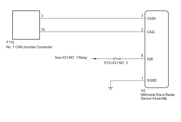
CAUTION / NOTICE / HINT
NOTICE:
- Because the order of diagnosis is important to allow correct diagnosis,
make sure to begin troubleshooting using How to Proceed with Troubleshooting
when CAN communication system related DTCs are output.
Click here
.gif)
- Before measuring the resistance of the CAN bus, turn the ignition switch off and leave the vehicle for 1 minute or more without operating the key or any switches, or opening or closing the doors. After that, disconnect the cable from the negative (-) battery terminal and leave the vehicle for 1 minute or more before measuring the resistance.
- After turning the ignition switch off, waiting time may be required
before disconnecting the cable from the negative (-) battery terminal. Therefore,
make sure to read the disconnecting the cable from the negative (-) battery
terminal notices before proceeding with work.
Click here
- After performing repairs, perform the DTC check procedure and confirm
that the DTCs are not output again.
DTC check procedure: Turn the cruise control main switch on and then drive the vehicle at a speed of 40 km/h (25 mph) or more for approximately 10 seconds or more.
- After the repair, perform the CAN bus check and check that all the ECUs
and sensors connected to the CAN communication system are displayed as normal.
Click here
- Inspect the fuses for circuits related to this system before performing the following procedure.
HINT:
- Before disconnecting related connectors for inspection, push in on each connector body to check that the connector is not loose or disconnected.
- When a connector is disconnected, check that the terminals and connector body are not cracked, deformed or corroded.
PROCEDURE
|
1. |
CHECK FOR OPEN IN CAN BUS LINES (MILLIMETER WAVE RADAR SENSOR ASSEMBLY BRANCH LINE) |
(a) Disconnect the cable from the negative (-) battery terminal.
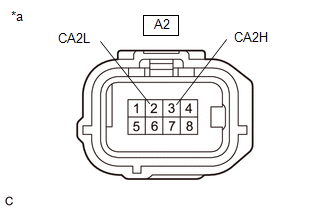
(b) Disconnect the millimeter wave radar sensor assembly connector.
|
(c) Measure the resistance according to the value(s) in the table below. Standard Resistance:
|
|
| NG | .gif) |
REPAIR OR REPLACE CAN BRANCH LINES OR CONNECTOR (MILLIMETER WAVE RADAR SENSOR ASSEMBLY) |
|
.gif)
|
2. |
CHECK HARNESS AND CONNECTOR (POWER SOURCE CIRCUIT) |
|
(a) Measure the resistance according to the value(s) in the table below. Standard Resistance:
|
|
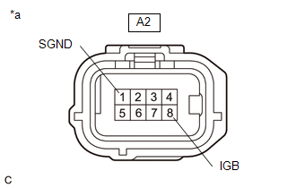
(b) Reconnect the cable to the negative (-) battery terminal.
(c) Measure the voltage according to the value(s) in the table below.
Standard Voltage:
|
Tester Connection |
Switch Condition |
Specified Condition |
|---|---|---|
|
A2-8 (IGB) - Body ground |
Ignition switch ON |
11 to 14 V |
| OK | |
REPLACE MILLIMETER WAVE RADAR SENSOR ASSEMBLY |
| NG | |
REPAIR OR REPLACE HARNESS OR CONNECTOR (POWER SOURCE CIRCUIT) |
 DCM Communication Stop Mode
DESCRIPTION
Detection Item
Symptom
Trouble Area
DCM Communication Stop Mode
Any of the following conditions are met:
Communi ...
 Open in Bus 1 Main Bus Line
DESCRIPTION
There may be an open circuit in one of the CAN main bus lines when the resistance
between terminals 23 (CA1H) and 8 (CA1L) of the central gateway ECU (network gateway
ECU) is 70 Ω or ...
Other materials:
Toyota CH-R Service Manual > Brake Pedal: Adjustment
ADJUSTMENT
PROCEDURE
1. INSPECT AND ADJUST BRAKE PEDAL HEIGHT
(a) Remove the No. 1 air duct.
Click here
(b) Check the brake pedal height.
NOTICE:
Inspect and adjust the brake pedal height with the floor carpet folded
back.
When performing the measurement, make sure that th ...
Toyota CH-R Service Manual > Electric Parking Brake System: Electric Current of Motor (C13A5,C13B0)
DESCRIPTION
The following DTCs are stored when a malfunction occurs in the skid control ECU
(brake actuator assembly).
DTC No.
Detection Item
DTC Detection Condition
Trouble Area
Memory
Note
C13A5
Elect ...
Toyota C-HR (AX20) 2023-2026 Owner's Manual
Toyota CH-R Owners Manual
- For safety and security
- Instrument cluster
- Operation of each component
- Driving
- Interior features
- Maintenance and care
- When trouble arises
- Vehicle specifications
- For owners
Toyota CH-R Service Manual
- Introduction
- Maintenance
- Audio / Video
- Cellular Communication
- Navigation / Multi Info Display
- Park Assist / Monitoring
- Brake (front)
- Brake (rear)
- Brake Control / Dynamic Control Systems
- Brake System (other)
- Parking Brake
- Axle And Differential
- Drive Shaft / Propeller Shaft
- K114 Cvt
- 3zr-fae Battery / Charging
- Networking
- Power Distribution
- Power Assist Systems
- Steering Column
- Steering Gear / Linkage
- Alignment / Handling Diagnosis
- Front Suspension
- Rear Suspension
- Tire / Wheel
- Tire Pressure Monitoring
- Door / Hatch
- Exterior Panels / Trim
- Horn
- Lighting (ext)
- Mirror (ext)
- Window / Glass
- Wiper / Washer
- Door Lock
- Heating / Air Conditioning
- Interior Panels / Trim
- Lighting (int)
- Meter / Gauge / Display
- Mirror (int)
- Power Outlets (int)
- Pre-collision
- Seat
- Seat Belt
- Supplemental Restraint Systems
- Theft Deterrent / Keyless Entry

0.0075