Toyota CH-R Service Manual: DCM Communication Stop Mode
DESCRIPTION
|
Detection Item |
Symptom |
Trouble Area |
|---|---|---|
|
DCM Communication Stop Mode |
Any of the following conditions are met:
|
|
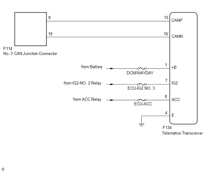
WIRING DIAGRAM
CAUTION / NOTICE / HINT
NOTICE:
- Before measuring the resistance of the CAN bus, turn the ignition switch off and leave the vehicle for 1 minute or more without operating the key, switches or opening or closing the doors. After that, disconnect the cable from the negative (-) battery terminal and leave the vehicle for 1 minute or more before measuring the resistance.
- After turning the ignition switch off, waiting time may be required
before disconnecting the cable from the negative (-) battery terminal. Therefore,
make sure to read the disconnecting the cable from the negative (-) battery
terminal notices before proceeding with work.
Click here
.gif)
- Because the order of diagnosis is important to allow correct diagnosis,
make sure to begin troubleshooting using How to Proceed with Troubleshooting
when CAN communication system related DTCs are output.
Click here
- After performing repairs, perform the DTC check procedure and confirm that the DTCs are not output again.
- DTC check procedure: Turn the ignition switch ON and wait for at least approximately 20 seconds.
- After the repair, perform the CAN bus check and check that all the ECUs
and sensors connected to the CAN communication system are displayed as normal.
Click here
- Inspect the fuses for circuits related to this system before performing the following procedure.
HINT:
- Operating the ignition switch, any other switches or a door triggers related ECU and sensor communication on the CAN. This communication will cause the resistance value to change.
- Even after DTCs are cleared, if a DTC is stored again after driving the vehicle for a while, the malfunction may be occurring due to vibration of the vehicle. In such a case, wiggling the ECUs or wire harness while performing the inspection below may help determine the cause of the malfunction.
PROCEDURE
|
1. |
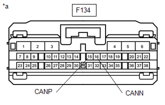
CHECK FOR OPEN IN CAN BUS LINES (TELEMATICS TRANSCEIVER BRANCH LINE) |
(a) Disconnect the cable from the negative (-) battery terminal.
(b) Disconnect the telematics transceiver connector.
|
(c) Measure the resistance according to the value(s) in the table below. Standard Resistance:
|
|
| NG | .gif) |
REPAIR OR REPLACE CAN BRANCH LINES OR CONNECTOR (TELEMATICS TRANSCEIVER) |
|
.gif)
|
2. |
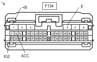
CHECK HARNESS AND CONNECTOR (POWER SOURCE CIRCUIT) |
|
(a) Measure the resistance according to the value(s) in the table below. Standard Resistance:
|
|
(b) Reconnect the cable to the negative (-) battery terminal.
(c) Measure the voltage according to the value(s) in the table below.
Standard Voltage:
|
Tester Connection |
Switch Condition |
Specified Condition |
|---|---|---|
|
F134-1 (+B) - Body ground |
Always |
11 to 14 V |
|
F134-7 (IG2) - Body ground |
Ignition switch ON |
11 to 14 V |
|
F134-8 (ACC) - Body ground |
Ignition switch ACC |
11 to 14 V |
| OK | |
REPLACE TELEMATICS TRANSCEIVER |
| NG | |
REPAIR OR REPLACE HARNESS OR CONNECTOR (POWER SOURCE CIRCUIT) |
 Blind Spot Monitor Sensor Communication Stop Mode
DESCRIPTION
Detection Item
Symptom
Trouble Area
Blind Spot Monitor Sensor Communication Stop Mode
Any of the following conditions are met: ...
 Millimeter Wave Radar Sensor Communication Stop Mode
DESCRIPTION
Detection Item
Symptom
Trouble Area
Millimeter Wave Radar Sensor Communication Stop Mode
Any of the following conditions are m ...
Other materials:
Toyota CH-R Service Manual > Vehicle Stability Control System: Skid Control ECU Malfunction (C1300)
DESCRIPTION
The skid control ECU (brake actuator assembly) stores this DTC if malfunctions
are found in a circuit inside the ECU by self diagnosis.
DTC No.
Detection Item
DTC Detection Condition
Trouble Area
C1300
Skid Contr ...
Toyota CH-R Owners Manual > Using the air conditioning system and defogger: Seat heaters
Seat heaters heat the front seats.
WARNING
Care should be taken to prevent injury if anyone in the following categories
comes in contact with the seats when the heater is on:
Babies, small children, the elderly, the sick and the physically
challenged
Persons with sensitive sk ...
Toyota C-HR (AX20) 2023-2026 Owner's Manual
Toyota CH-R Owners Manual
- For safety and security
- Instrument cluster
- Operation of each component
- Driving
- Interior features
- Maintenance and care
- When trouble arises
- Vehicle specifications
- For owners
Toyota CH-R Service Manual
- Introduction
- Maintenance
- Audio / Video
- Cellular Communication
- Navigation / Multi Info Display
- Park Assist / Monitoring
- Brake (front)
- Brake (rear)
- Brake Control / Dynamic Control Systems
- Brake System (other)
- Parking Brake
- Axle And Differential
- Drive Shaft / Propeller Shaft
- K114 Cvt
- 3zr-fae Battery / Charging
- Networking
- Power Distribution
- Power Assist Systems
- Steering Column
- Steering Gear / Linkage
- Alignment / Handling Diagnosis
- Front Suspension
- Rear Suspension
- Tire / Wheel
- Tire Pressure Monitoring
- Door / Hatch
- Exterior Panels / Trim
- Horn
- Lighting (ext)
- Mirror (ext)
- Window / Glass
- Wiper / Washer
- Door Lock
- Heating / Air Conditioning
- Interior Panels / Trim
- Lighting (int)
- Meter / Gauge / Display
- Mirror (int)
- Power Outlets (int)
- Pre-collision
- Seat
- Seat Belt
- Supplemental Restraint Systems
- Theft Deterrent / Keyless Entry

0.0098