Toyota CH-R Service Manual: Installation
INSTALLATION
PROCEDURE
1. INSTALL PARK/NEUTRAL POSITION SWITCH
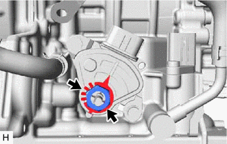
(a) Temporarily install the park/neutral position switch to the continuously variable transaxle assembly with the 2 bolts.
|
(b) Install the lock plate and lock nut to the park/neutral position switch. Torque: 6.9 N·m {70 kgf·cm, 61 in·lbf} |
|
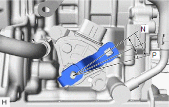
(c) Temporarily install the control shaft lever to the park/neutral position switch.
|
(d) Turn the control shaft lever clockwise until it stops, then turn it counterclockwise 2 notches. |
|
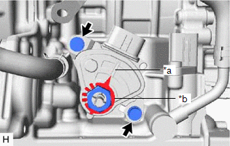
(e) Remove the control shaft lever from the park/neutral position switch.
|
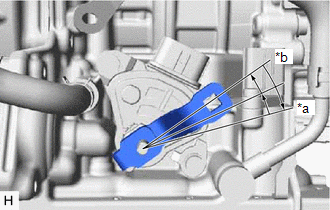
(f) Align the protrusion with the neutral basic line. |
|
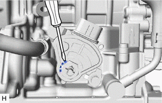
(g) Hold the park/neutral position switch in that position and tighten the 2 bolts.
Torque:
5.4 N·m {55 kgf·cm, 48 in·lbf}
|
(h) Using a screwdriver, stake the lock nut with the lock plate. |
|
(i) Install the control shaft lever to the park/neutral position switch with the washer and nut.
Torque:
12.7 N·m {130 kgf·cm, 9 ft·lbf}
(j) Connect the park/neutral position switch connector.
2. CONNECT TRANSMISSION CONTROL CABLE ASSEMBLY
(a) Connect the transmission control cable assembly to the No. 1 transmission control cable bracket with a new clip.
|
(b) Turn the control shaft lever clockwise until it stops, then turn it counterclockwise 2 notches. |
|
(c) Connect the transmission control cable assembly to the control shaft lever with the nut.
Torque:
12 N·m {122 kgf·cm, 9 ft·lbf}
3. INSPECT SHIFT LEVER POSITION
Click here
.gif)
4. ADJUST SHIFT LEVER POSITION
Click here
5. INSPECT PARK/NEUTRAL POSITION SWITCH OPERATION
Click here
6. ADJUST PARK/NEUTRAL POSITION SWITCH
Click here
7. INSTALL AIR CLEANER CASE SUB-ASSEMBLY
Click here
8. INSTALL AIR CLEANER CAP WITH AIR CLEANER HOSE
Click here
9. INSTALL NO. 1 AIR CLEANER INLET
Click here
10. INSTALL RADIATOR COVER
Click here
11. INSTALL NO. 2 CYLINDER HEAD COVER
Click here
12. INSTALL REAR ENGINE UNDER COVER LH
Click here
13. INSTALL NO. 1 ENGINE UNDER COVER
Click here
 Adjustment
ADJUSTMENT
PROCEDURE
1. ADJUST PARK/NEUTRAL POSITION SWITCH
(a) Apply the parking brake and move the shift lever to N.
(b) Loosen the 2 bolts of the park/neutral position switch.
...

Other materials:
Toyota CH-R Service Manual > Brake Pedal: Installation
INSTALLATION
PROCEDURE
1. INSTALL BRAKE PEDAL PAD
(a) Install the brake pedal pad from the brake pedal support assembly.
2. INSTALL BRAKE PEDAL SUPPORT ASSEMBLY
(a) Install the nut to the brake pedal support assembly.
(b) Temporarily install the brake pedal support assembly with 2 n ...
Toyota CH-R Service Manual > Tire Pressure Warning System: Precaution
PRECAUTION
IGNITION SWITCH EXPRESSIONS
(a) The type of ignition switch used on this model differs according to the specifications
of the vehicle. The expressions listed in the table below are used in this section.
Expression
Ignition Switch (Position)
Engine Swi ...
Toyota C-HR (AX20) 2023-2026 Owner's Manual
Toyota CH-R Owners Manual
- For safety and security
- Instrument cluster
- Operation of each component
- Driving
- Interior features
- Maintenance and care
- When trouble arises
- Vehicle specifications
- For owners
Toyota CH-R Service Manual
- Introduction
- Maintenance
- Audio / Video
- Cellular Communication
- Navigation / Multi Info Display
- Park Assist / Monitoring
- Brake (front)
- Brake (rear)
- Brake Control / Dynamic Control Systems
- Brake System (other)
- Parking Brake
- Axle And Differential
- Drive Shaft / Propeller Shaft
- K114 Cvt
- 3zr-fae Battery / Charging
- Networking
- Power Distribution
- Power Assist Systems
- Steering Column
- Steering Gear / Linkage
- Alignment / Handling Diagnosis
- Front Suspension
- Rear Suspension
- Tire / Wheel
- Tire Pressure Monitoring
- Door / Hatch
- Exterior Panels / Trim
- Horn
- Lighting (ext)
- Mirror (ext)
- Window / Glass
- Wiper / Washer
- Door Lock
- Heating / Air Conditioning
- Interior Panels / Trim
- Lighting (int)
- Meter / Gauge / Display
- Mirror (int)
- Power Outlets (int)
- Pre-collision
- Seat
- Seat Belt
- Supplemental Restraint Systems
- Theft Deterrent / Keyless Entry

0.008