Toyota CH-R Service Manual: Start Up Signal Circuit between Radio Receiver Assembly and Navigation ECU
DESCRIPTION
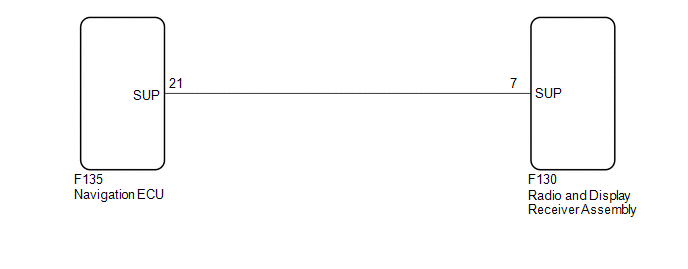
This circuit includes the navigation ECU and radio and display receiver assembly.
WIRING DIAGRAM
PROCEDURE
|
1. |
CHECK HARNESS AND CONNECTOR (RADIO AND DISPLAY RECEIVER ASSEMBLY - NAVIGATION ECU) |
(a) Disconnect the F130 radio and display receiver assembly connector.
(b) Disconnect the F135 navigation ECU connector.
(c) Measure the resistance according to the value(s) in the table below.
Standard Resistance:
|
Tester Connection |
Condition |
Specified Condition |
|---|---|---|
|
F130-7 (SUP) - F135-21 (SUP) |
Always |
Below 1 Ω |
|
F130-7 (SUP) or F135-21 (SUP) - Body ground |
Always |
10 kΩ or higher |
| OK | .gif) |
PROCEED TO NEXT SUSPECTED AREA SHOWN IN PROBLEM SYMPTOMS TABLE |
| NG | |
REPAIR OR REPLACE HARNESS OR CONNECTOR |
 Reverse Signal Circuit between Radio Receiver Assembly and Navigation ECU
DESCRIPTION
This circuit includes the navigation ECU and radio and display receiver assembly.
WIRING DIAGRAM
PROCEDURE
1.
CHECK HARNESS AND CONNECTOR (RADIO AND DISPLAY RE ...
 Microphone Circuit
DESCRIPTION
The radio and display receiver assembly, map light assembly and telephone microphone
assembly are connected to each other using the microphone connection detection signal
lines.
Usin ...
Other materials:
Toyota CH-R Service Manual > Meter / Gauge System: Lost Communication with ECM / PCM "A" (U0100,U0129,U0131,U0142,U0151,U0182,U0235,U023A)
DESCRIPTION
The combination meter assembly communicates with the ECM, brake actuator assembly
(skid control ECU), power steering ECU assembly, main body ECU (multiplex network
body ECU), airbag sensor assembly, headlight control ECU sub-assembly LH*1, front
camera module*2, millimeter wave ra ...
Toyota CH-R Service Manual > Toyota Entune System: Lost Communication with Body Control Module "B" (U0142,U0155,U0163)
DESCRIPTION
These DTCs are stored when a malfunction occurs in the CAN communication circuit.
HINT:
If CAN communication system DTCs are stored, they may also be stored for other
systems.
DTC No.
Detection Item
DTC Detection Condition
Trouble Area
...
Toyota C-HR (AX20) 2023-2026 Owner's Manual
Toyota CH-R Owners Manual
- For safety and security
- Instrument cluster
- Operation of each component
- Driving
- Interior features
- Maintenance and care
- When trouble arises
- Vehicle specifications
- For owners
Toyota CH-R Service Manual
- Introduction
- Maintenance
- Audio / Video
- Cellular Communication
- Navigation / Multi Info Display
- Park Assist / Monitoring
- Brake (front)
- Brake (rear)
- Brake Control / Dynamic Control Systems
- Brake System (other)
- Parking Brake
- Axle And Differential
- Drive Shaft / Propeller Shaft
- K114 Cvt
- 3zr-fae Battery / Charging
- Networking
- Power Distribution
- Power Assist Systems
- Steering Column
- Steering Gear / Linkage
- Alignment / Handling Diagnosis
- Front Suspension
- Rear Suspension
- Tire / Wheel
- Tire Pressure Monitoring
- Door / Hatch
- Exterior Panels / Trim
- Horn
- Lighting (ext)
- Mirror (ext)
- Window / Glass
- Wiper / Washer
- Door Lock
- Heating / Air Conditioning
- Interior Panels / Trim
- Lighting (int)
- Meter / Gauge / Display
- Mirror (int)
- Power Outlets (int)
- Pre-collision
- Seat
- Seat Belt
- Supplemental Restraint Systems
- Theft Deterrent / Keyless Entry

0.0098