Toyota CH-R Service Manual: Electric Parking Brake Switch
Components
COMPONENTS
ILLUSTRATION
|
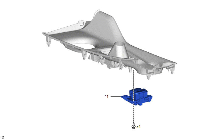
*1 |
ELECTRIC PARKING BRAKE SWITCH ASSEMBLY |
- |
- |
Removal
REMOVAL
PROCEDURE
1. PRECAUTION
Click here
.gif)
2. REMOVE CONSOLE UPPER PANEL SUB-ASSEMBLY
Click here
3. REMOVE ELECTRIC PARKING BRAKE SWITCH ASSEMBLY
|
(a) Remove the 4 screws. |
|
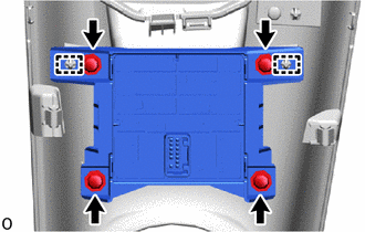
(b) Disengage the 2 guides to remove the electric parking brake switch assembly.
Inspection
INSPECTION
PROCEDURE
1. INSPECT ELECTRIC PARKING BRAKE SWITCH ASSEMBLY
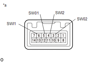
(a) Check the resistance.
|
(1) Measure the resistance according to the value(s) in the table below. Standard Resistance:
If the result is not as specified, replace the electric parking brake switch assembly. |
|
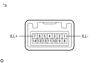
(b) Check the Illuminates.
|
(1) Apply battery voltage to the electric parking brake switch assembly and check that the switch illuminates. OK:
If the result is not as specified, replace the electric parking brake switch assembly. |
|
Installation
INSTALLATION
PROCEDURE
1. INSTALL ELECTRIC PARKING BRAKE SWITCH ASSEMBLY
(a) Engage the 2 guides to install the electric parking brake switch assembly.
(b) Install the 4 screws.
2. INSTALL CONSOLE UPPER PANEL SUB-ASSEMBLY
Click here
.gif)
 Installation
INSTALLATION
CAUTION / NOTICE / HINT
HINT:
Use the same procedure for the RH side and LH side.
The following procedure is for the LH side.
PROCEDURE
1. INSTALL PARKING BRAKE ACT ...

Other materials:
Toyota CH-R Service Manual > Air Conditioning Amplifier: Removal
REMOVAL
CAUTION / NOTICE / HINT
The necessary procedures (adjustment, calibration, initialization or registration)
that must be performed after parts are removed and installed, or replaced during
the air conditioning amplifier assembly removal/installation are shown below.
Necessary Procedure ...
Toyota CH-R Service Manual > 3zr-fae Oil And Oil Filter: Replacement
REPLACEMENT
CAUTION / NOTICE / HINT
CAUTION:
Prolonged and repeated contact with engine oil will result in the removal
of natural oils from the skin, leading to dryness, irritation and dermatitis.
In addition, used engine oil contains potentially harmful contaminants which
may ...
Toyota C-HR (AX20) 2023-2026 Owner's Manual
Toyota CH-R Owners Manual
- For safety and security
- Instrument cluster
- Operation of each component
- Driving
- Interior features
- Maintenance and care
- When trouble arises
- Vehicle specifications
- For owners
Toyota CH-R Service Manual
- Introduction
- Maintenance
- Audio / Video
- Cellular Communication
- Navigation / Multi Info Display
- Park Assist / Monitoring
- Brake (front)
- Brake (rear)
- Brake Control / Dynamic Control Systems
- Brake System (other)
- Parking Brake
- Axle And Differential
- Drive Shaft / Propeller Shaft
- K114 Cvt
- 3zr-fae Battery / Charging
- Networking
- Power Distribution
- Power Assist Systems
- Steering Column
- Steering Gear / Linkage
- Alignment / Handling Diagnosis
- Front Suspension
- Rear Suspension
- Tire / Wheel
- Tire Pressure Monitoring
- Door / Hatch
- Exterior Panels / Trim
- Horn
- Lighting (ext)
- Mirror (ext)
- Window / Glass
- Wiper / Washer
- Door Lock
- Heating / Air Conditioning
- Interior Panels / Trim
- Lighting (int)
- Meter / Gauge / Display
- Mirror (int)
- Power Outlets (int)
- Pre-collision
- Seat
- Seat Belt
- Supplemental Restraint Systems
- Theft Deterrent / Keyless Entry

0.0075