Toyota CH-R Service Manual: Installation
INSTALLATION
PROCEDURE
1. INSTALL VACUUM PUMP ASSEMBLY
(a) When installing a new vacuum pump assembly:
|
(1) Apply engine oil to the No. 2 O-ring and No. 3 O-ring which are installed to a new vacuum pump assembly. |
|
.png)
(b) When reusing the vacuum pump assembly:
|
(1) Apply engine oil to a new No. 2 O-ring and No. 3 O-ring and install them to the vacuum pump assembly. |
|
(c) Apply engine oil to the inner surface of the installation hole.
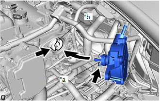
|
*a |
Coupling Teeth |
|
*b |
Groove |
.png) |
Engine Oil |
(d) Install the vacuum pump assembly so that the coupling teeth of the vacuum pump assembly and the groove of the camshaft are engaged.
NOTICE:
Ensure that the vacuum pump assembly is installed securely.
|
(e) Install the 3 bolts. Torque: 21 N·m {214 kgf·cm, 15 ft·lbf} NOTICE: After tightening the bolts, ensure that the contact surface of the vacuum pump assembly is flush with the cylinder head. Length of the Bolt
|
|
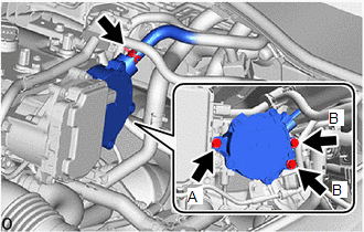
(f) Connect the union to connector tube hose to the vacuum pump assembly and slide the clip to secure it.
2. CONNECT UNION TO CONNECTOR TUBE HOSE
(a) Connect the union to connector tube hose to the vacuum pump assembly and slide the clip to secure it.
3. CONNECT ENGINE WIRE
Click here
.gif)
4. INSTALL NO. 2 CYLINDER HEAD COVER
Click here
5. INSTALL BATTERY
Click here
6. OPERATION CHECK
Click here
 Reassembly
REASSEMBLY
PROCEDURE
1. INSTALL VACUUM PUMP VANE
(a) Apply engine oil to the vacuum pump vane and 2 vacuum pump vane caps.
(b) Install the vacuum pump vane caps to the vacuum pump vane. ...

Other materials:
Toyota CH-R Service Manual > Door Control Transmitter(w/ Smart Key System): Installation
INSTALLATION
CAUTION / NOTICE / HINT
NOTICE:
Take extra care when handling these precision electronic components.
PROCEDURE
1. INSTALL TRANSMITTER BATTERY
(a) Install a new transmitter battery with the positive (+) side facing upward,
as shown in the illustration.
NOTICE:
Do not be ...
Toyota CH-R Owners Manual > Operation of each component: Key information
The keys
The following keys are provided with the vehicle.
Vehicles without a smart key system (type A)
Key (with a wireless remote control function)
Operating the wireless remote control function
Key (without a wireless remote control function)
Key number plate
Vehicles without a ...
Toyota C-HR (AX20) 2023-2026 Owner's Manual
Toyota CH-R Owners Manual
- For safety and security
- Instrument cluster
- Operation of each component
- Driving
- Interior features
- Maintenance and care
- When trouble arises
- Vehicle specifications
- For owners
Toyota CH-R Service Manual
- Introduction
- Maintenance
- Audio / Video
- Cellular Communication
- Navigation / Multi Info Display
- Park Assist / Monitoring
- Brake (front)
- Brake (rear)
- Brake Control / Dynamic Control Systems
- Brake System (other)
- Parking Brake
- Axle And Differential
- Drive Shaft / Propeller Shaft
- K114 Cvt
- 3zr-fae Battery / Charging
- Networking
- Power Distribution
- Power Assist Systems
- Steering Column
- Steering Gear / Linkage
- Alignment / Handling Diagnosis
- Front Suspension
- Rear Suspension
- Tire / Wheel
- Tire Pressure Monitoring
- Door / Hatch
- Exterior Panels / Trim
- Horn
- Lighting (ext)
- Mirror (ext)
- Window / Glass
- Wiper / Washer
- Door Lock
- Heating / Air Conditioning
- Interior Panels / Trim
- Lighting (int)
- Meter / Gauge / Display
- Mirror (int)
- Power Outlets (int)
- Pre-collision
- Seat
- Seat Belt
- Supplemental Restraint Systems
- Theft Deterrent / Keyless Entry

0.0091