Toyota CH-R Service Manual: Components
COMPONENTS
ILLUSTRATION
|
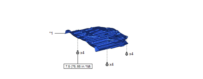
*1 |
NO. 1 ENGINE UNDER COVER |
- |
- |
.png) |
N*m (kgf*cm, ft.*lbf): Specified torque |
- |
- |
ILLUSTRATION
|
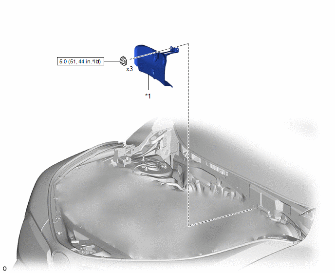
*1 |
DASH PANEL HEAT INSULATOR |
- |
- |
|
|
N*m (kgf*cm, ft.*lbf): Specified torque |
- |
- |
ILLUSTRATION
|
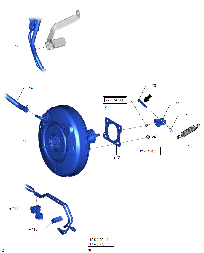
*1 |
BRAKE BOOSTER ASSEMBLY |
*2 |
BRAKE BOOSTER GASKET |
|
*3 |
BRAKE PEDAL RETURN SPRING |
*4 |
CHECK VALVE TO CONNECTOR TUBE HOSE |
|
*5 |
CLEVIS LOCK NUT |
*6 |
PUSH ROD PIN |
|
*7 |
FUEL PIPE |
*8 |
BRAKE TUBE |
|
*9 |
BRAKE MASTER CYLINDER PUSH ROD CLEVIS |
*10 |
NO. 1 BRAKE TUBE CLAMP |
|
*11 |
NO. 2 BRAKE TUBE CLAMP |
- |
- |
.png) |
Tightening torque for "Major areas involving basic vehicle performance such as moving/turning/stopping" : N*m (kgf*cm, ft.*lbf) |
● |
Non-reusable part |
.png) |
Lithium soap base glycol grease |
- |
- |
ILLUSTRATION
|
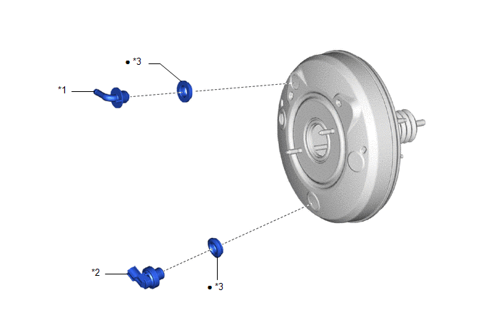
*1 |
BRAKE VACUUM CHECK VALVE ASSEMBLY |
*2 |
VACUUM WARNING SWITCH ASSEMBLY |
|
*3 |
CHECK VALVE GROMMET |
- |
- |
|
● |
Non-reusable part |
- |
- |
 Brake Booster
...
 On-vehicle Inspection
ON-VEHICLE INSPECTION
PROCEDURE
1. INSPECT BRAKE BOOSTER ASSEMBLY
(a) Airtightness check
(1) Start the engine and stop it after 1 or 2 minutes. Slowly depress
the brake pedal severa ...
Other materials:
Toyota CH-R Service Manual > Windshield Deicer System: System Description
SYSTEM DESCRIPTION
GENERAL
The windshield deicer thin heater wires are attached to the inside of the windshield
glass to help deice the window surface more quickly. The indicator light illuminates
while the system is operating. The system automatically turns off after approximately
15 minute ...
Toyota CH-R Service Manual > Air Conditioning System(for Automatic Air Conditioning System With Side-mounted
Air Conditioner Pressure Sensor): Diagnostic Trouble Code Chart
DIAGNOSTIC TROUBLE CODE CHART
AIR CONDITIONING SYSTEM
DTC No.
Detection Item
DTC Detection Condition
Link
B1411
Room Temperature Sensor Circuit
Any of the following conditions is met:
Open in cooler th ...
Toyota C-HR (AX20) 2023-2026 Owner's Manual
Toyota CH-R Owners Manual
- For safety and security
- Instrument cluster
- Operation of each component
- Driving
- Interior features
- Maintenance and care
- When trouble arises
- Vehicle specifications
- For owners
Toyota CH-R Service Manual
- Introduction
- Maintenance
- Audio / Video
- Cellular Communication
- Navigation / Multi Info Display
- Park Assist / Monitoring
- Brake (front)
- Brake (rear)
- Brake Control / Dynamic Control Systems
- Brake System (other)
- Parking Brake
- Axle And Differential
- Drive Shaft / Propeller Shaft
- K114 Cvt
- 3zr-fae Battery / Charging
- Networking
- Power Distribution
- Power Assist Systems
- Steering Column
- Steering Gear / Linkage
- Alignment / Handling Diagnosis
- Front Suspension
- Rear Suspension
- Tire / Wheel
- Tire Pressure Monitoring
- Door / Hatch
- Exterior Panels / Trim
- Horn
- Lighting (ext)
- Mirror (ext)
- Window / Glass
- Wiper / Washer
- Door Lock
- Heating / Air Conditioning
- Interior Panels / Trim
- Lighting (int)
- Meter / Gauge / Display
- Mirror (int)
- Power Outlets (int)
- Pre-collision
- Seat
- Seat Belt
- Supplemental Restraint Systems
- Theft Deterrent / Keyless Entry

0.0082