Toyota CH-R Service Manual: Stop Light Control Relay Malfunction (C1380)
DESCRIPTION
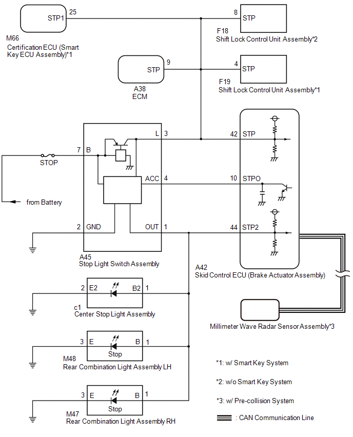
When the dynamic radar cruise control system*1, pre-collision system*1 or brake hold control system operates, the skid control ECU outputs a stop light drive output (STPO) signal to illuminate the stop lights.
*1: w/ Pre-collision System
|
DTC No. |
Detection Item |
DTC Detection Condition |
Trouble Area |
|---|---|---|---|
|
C1380 |
Stop Light Control Relay Malfunction |
Either condition is met:
|
|
|
Vehicle Condition |
|||
|---|---|---|---|
|
Pattern 1 |
Pattern 2 |
||
|
Diagnosis Condition |
- |
- |
- |
|
Malfunction Status |
When the voltage at the +BS terminal is between 10 V or more and the stop light control relay drive output (STPO) is on, a signal is not input to the STP2 terminal. |
○ |
- |
|
When the voltage at the +BS terminal is between 10 V or more and the stop light control relay drive output (STPO) is off, the signal at the STP terminal is different from the input signal at the STP2 terminal. |
- |
○ |
|
|
Detection Time |
5 seconds or more |
5 seconds or more |
|
|
Number of Trips |
1 trip |
1 trip |
|
HINT:
DTC will be output when conditions for either of the patterns in the table above are met.
WIRING DIAGRAM
CAUTION / NOTICE / HINT
NOTICE:
- When replacing the skid control ECU (brake actuator assembly), perform
system variant learning.
Click here
.gif)
- Inspect the fuses for circuits related to this system before performing the following procedure.
PROCEDURE
|
1. |
CHECK HARNESS AND CONNECTOR (STP, STPO AND STP2 TERMINAL) |
(a) Turn the ignition switch off.
|
(b) Disconnect the skid control ECU (brake actuator assembly) connector. |
|
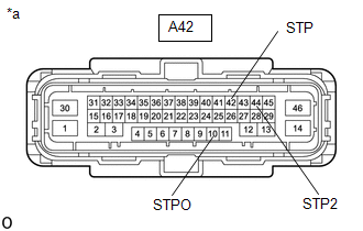
(c) Measure the voltage according to the value(s) in the table below.
Standard Voltage:
|
Tester Connection |
Condition |
Specified Condition |
|---|---|---|
|
A42-42 (STP) - Body ground |
Brake pedal depressed |
11 to 14 V |
|
Brake pedal released |
Below 1.5 V |
|
|
A42-10 (STPO) - Body ground |
Always |
11 to 14 V |
|
A42-44 (STP2) - Body ground |
Brake pedal depressed |
11 to 14 V |
|
Brake pedal released |
Below 1.5 V |
|
Result |
Proceed to |
|---|---|
|
All terminal voltage is normal |
A |
|
Only STP terminal voltage abnormal |
B |
|
Only STPO terminal voltage abnormal |
C |
|
Only STP2 terminal voltage abnormal |
D |
|
STPO terminal and STP2 terminal voltage abnormal |
E |
| B | .gif) |
GO TO STEP 5 |
| C | |
GO TO STEP 13 |
| D | |
GO TO STEP 14 |
| E | |
GO TO STEP 18 |
|
.gif)
|
2. |
PERFORM ACTIVE TEST USING TECHSTREAM (STOP LIGHT RELAY) |
(a) Enter the following menus: Chassis / ABS/VSC/TRAC/EPB / Active Test.
(b) Perform "Active Test" according to the display on the Techstream.
Chassis > ABS/VSC/TRAC/EPB > Active Test|
Tester Display |
Measurement Item |
Control Range |
Diagnostic Note |
|---|---|---|---|
|
Stop Light Relay |
Stop light control relay (Stop light switch assembly) |
ON or OFF |
Stop lights come on |
|
Tester Display |
|---|
|
Stop Light Relay |
OK:
Stop light turns ON/OFF in response to the Techstream operation
| NG | |
GO TO STEP 4 |
|
|
3. |
CHECK FOR DTC |
(a) Clear the DTCs.
Click here
(b) Enter the following menus: Chassis / ABS/VSC/TRAC/EPB / Active Test.
(c) Perform "Active Test" according to the display on the Techstream.
Chassis > ABS/VSC/TRAC/EPB > Active Test|
Tester Display |
Measurement Item |
Control Range |
Diagnostic Note |
|---|---|---|---|
|
Stop Light Relay |
Stop light control relay (Stop light switch assembly) |
ON or OFF |
Stop lights come on |
|
Tester Display |
|---|
|
Stop Light Relay |
(d) Check for DTCs.
Click here
|
Result |
Proceed to |
|---|---|
|
DTC C1380 is output. |
A |
|
DTC C1380 is not output. |
B |
| A | |
REPLACE BRAKE ACTUATOR ASSEMBLY |
| B | |
USE SIMULATION METHOD TO CHECK
|
|
4. |
INSPECT BRAKE ACTUATOR ASSEMBLY |
(a) Enter the following menus: Chassis / ABS/VSC/TRAC/EPB / Active Test.
(b) Perform "Active Test" according to the display on the Techstream.
Chassis > ABS/VSC/TRAC/EPB > Active Test|
Tester Display |
Measurement Item |
Control Range |
Diagnostic Note |
|---|---|---|---|
|
Stop Light Relay |
Stop light control relay (Stop light switch assembly) |
ON or OFF |
Stop lights come on |
|
Tester Display |
|---|
|
Stop Light Relay |
|
(c) Measure the voltage according to the value(s) in the table below. Standard Voltage:
|
|
| OK | |
REPLACE STOP LIGHT SWITCH ASSEMBLY |
| NG | |
REPLACE BRAKE ACTUATOR ASSEMBLY |
|
5. |
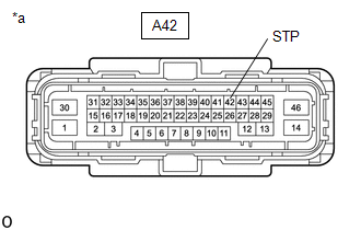
CHECK HARNESS AND CONNECTOR (BRAKE ACTUATOR ASSEMBLY - ECM) |
|
(a) Make sure that there is no looseness at the locking part and the connecting part of the connector. OK: The connector is securely connected. |
|
(b) Disconnect the A38 ECM connector.
(c) Check both the connector case and the terminals for deformation and corrosion.
OK:
No deformation or corrosion.
(d) Measure the voltage according to the value(s) in the table below.
Standard Voltage:
|
Tester Connection |
Condition |
Specified Condition |
|---|---|---|
|
A42-42 (STP) - Body ground |
Stop light switch assembly on (Brake pedal depressed) |
11 to 14 V* |
|
A42-42 (STP) - Body ground |
Stop light switch assembly off (Brake pedal released) |
Below 1.5 V |
HINT:
*: The standard voltage value varies depending on the +BS terminal voltage value. The standard voltage is 85% of the +BS terminal voltage.
|
Result |
Proceed to |
|---|---|
|
OK |
A |
|
NG (w/ Smart Key System) |
B |
|
NG (w/o Smart Key System) |
C |
| A | |
REPLACE ECM |
| C | |
GO TO STEP 10 |
|
|
6. |
CHECK HARNESS AND CONNECTOR (BRAKE ACTUATOR ASSEMBLY - SMART KEY ECU ASSEMBLY) |
|
(a) Make sure that there is no looseness at the locking part and the connecting part of the connector. OK: The connector is securely connected. |
|
(b) Disconnect the M66 certification ECU (smart key ECU assembly) connector.
(c) Check both the connector case and the terminals for deformation and corrosion.
OK:
No deformation or corrosion.
(d) Measure the voltage according to the value(s) in the table below.
Standard Voltage:
|
Tester Connection |
Condition |
Specified Condition |
|---|---|---|
|
A42-42 (STP) - Body ground |
Stop light switch assembly on (Brake pedal depressed) |
11 to 14 V* |
|
A42-42 (STP) - Body ground |
Stop light switch assembly off (Brake pedal released) |
Below 1.5 V |
HINT:
*: The standard voltage value varies depending on the +BS terminal voltage value. The standard voltage is 85% of the +BS terminal voltage.
| OK | |
REPLACE SMART KEY ECU ASSEMBLY |
|
|
7. |
CHECK HARNESS AND CONNECTOR (BRAKE ACTUATOR ASSEMBLY - SHIFT LOCK CONTROL UNIT ASSEMBLY) |
|
(a) Make sure that there is no looseness at the locking part and the connecting part of the connector. OK: The connector is securely connected. |
|
(b) Disconnect the F19 shift lock control ECU (shift lock control unit assembly) connector.
(c) Check both the connector case and the terminals for deformation and corrosion.
OK:
No deformation or corrosion.
(d) Measure the voltage according to the value(s) in the table below.
Standard Voltage:
|
Tester Connection |
Condition |
Specified Condition |
|---|---|---|
|
A42-42 (STP) - Body ground |
Stop light switch assembly on (Brake pedal depressed) |
11 to 14 V* |
|
A42-42 (STP) - Body ground |
Stop light switch assembly off (Brake pedal released) |
Below 1.5 V |
HINT:
*: The standard voltage value varies depending on the +BS terminal voltage value. The standard voltage is 85% of the +BS terminal voltage.
| OK | |
REPLACE SHIFT LOCK CONTROL UNIT ASSEMBLY |
|
|
8. |
CHECK HARNESS AND CONNECTOR (BRAKE ACTUATOR ASSEMBLY - STOP LIGHT SWITCH ASSEMBLY) |
|
(a) Make sure that there is no looseness at the locking part and the connecting part of the connector. OK: The connector is securely connected. |
|
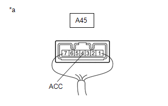
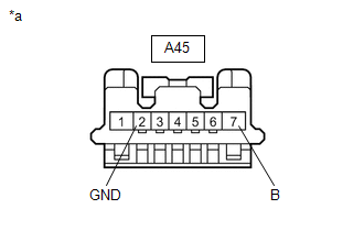
(b) Disconnect the A45 stop light switch assembly connector.
(c) Check both the connector case and the terminals for deformation and corrosion.
OK:
No deformation or corrosion.
(d) Measure the voltage according to the value(s) in the table below.
Standard Voltage:
|
Tester Connection |
Condition |
Specified Condition |
|---|---|---|
|
A42-42 (STP) - Body ground |
Always |
Below 1.5 V |
| NG | |
REPAIR OR REPLACE HARNESS OR CONNECTOR |
|
|
9. |
CHECK HARNESS AND CONNECTOR (BRAKE ACTUATOR ASSEMBLY - STOP LIGHT SWITCH ASSEMBLY) |
(a) Measure the resistance according to the value(s) in the table below.
Standard Resistance:
|
Tester Connection |
Condition |
Specified Condition |
|---|---|---|
|
A42-42 (STP) - A45-3 (L) |
Always |
Below 1 Ω |
|
A42-42 (STP) or A45-3 (L) - Body ground |
Always |
10 kΩ or higher |
| OK | |
REPLACE STOP LIGHT SWITCH ASSEMBLY |
| NG | |
REPAIR OR REPLACE HARNESS OR CONNECTOR |
|
10. |
CHECK HARNESS AND CONNECTOR (BRAKE ACTUATOR ASSEMBLY - SHIFT LOCK CONTROL UNIT ASSEMBLY) |
|
(a) Make sure that there is no looseness at the locking part and the connecting part of the connector. OK: The connector is securely connected. |
|
(b) Disconnect the F18 shift lock control ECU (shift lock control unit assembly) connector.
(c) Check both the connector case and the terminals for deformation and corrosion.
OK:
No deformation or corrosion.
(d) Measure the voltage according to the value(s) in the table below.
Standard Voltage:
|
Tester Connection |
Condition |
Specified Condition |
|---|---|---|
|
A42-42 (STP) - Body ground |
Stop light switch assembly on (Brake pedal depressed) |
11 to 14 V* |
|
A42-42 (STP) - Body ground |
Stop light switch assembly off (Brake pedal released) |
Below 1.5 V |
HINT:
*: The standard voltage value varies depending on the +BS terminal voltage value. The standard voltage is 85% of the +BS terminal voltage.
| OK | |
REPLACE SHIFT LOCK CONTROL UNIT ASSEMBLY |
|
|
11. |
CHECK HARNESS AND CONNECTOR (BRAKE ACTUATOR ASSEMBLY - STOP LIGHT SWITCH ASSEMBLY) |
|
(a) Make sure that there is no looseness at the locking part and the connecting part of the connector. OK: The connector is securely connected. |
|
(b) Disconnect the A45 stop light switch assembly connector.
(c) Check both the connector case and the terminals for deformation and corrosion.
OK:
No deformation or corrosion.
(d) Measure the voltage according to the value(s) in the table below.
Standard Voltage:
|
Tester Connection |
Condition |
Specified Condition |
|---|---|---|
|
A42-42 (STP) - Body ground |
Always |
Below 1.5 V |
| NG | |
REPAIR OR REPLACE HARNESS OR CONNECTOR |
|
|
12. |
CHECK HARNESS AND CONNECTOR (BRAKE ACTUATOR ASSEMBLY - STOP LIGHT SWITCH ASSEMBLY) |
(a) Measure the resistance according to the value(s) in the table below.
Standard Resistance:
|
Tester Connection |
Condition |
Specified Condition |
|---|---|---|
|
A42-42 (STP) - A45-3 (L) |
Always |
Below 1 Ω |
|
A42-42 (STP) or A45-3 (L) - Body ground |
Always |
10 kΩ or higher |
| OK | |
REPLACE STOP LIGHT SWITCH ASSEMBLY |
| NG | |
REPAIR OR REPLACE HARNESS OR CONNECTOR |
|
13. |
CHECK HARNESS AND CONNECTOR (BRAKE ACTUATOR ASSEMBLY - STOP LIGHT SWITCH ASSEMBLY) |
(a) Turn the ignition switch off.
(b) Disconnect the A42 skid control ECU (brake actuator assembly) connector.
(c) Disconnect the A45 stop light switch assembly connector.
(d) Measure the resistance according to the value(s) in the table below.
Standard Resistance:
|
Tester Connection |
Condition |
Specified Condition |
|---|---|---|
|
A42-10 (STPO) - A45-4 (ACC) |
Always |
Below 1 Ω |
| OK | |
REPLACE STOP LIGHT SWITCH ASSEMBLY |
| NG | |
REPAIR OR REPLACE HARNESS OR CONNECTOR |
|
14. |
CHECK HARNESS AND CONNECTOR (BRAKE ACTUATOR ASSEMBLY - REAR COMBINATION LIGHT ASSEMBLY LH) |
|
(a) Turn the ignition switch off. |
|
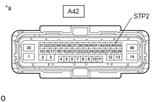
(b) Disconnect the A42 skid control ECU (brake actuator assembly) connector.
(c) Disconnect the M48 rear combination light assembly LH connector.
(d) Measure the voltage according to the value(s) in the table below.
Standard Voltage:
|
Tester Connection |
Condition |
Specified Condition |
|---|---|---|
|
A42-44 (STP2) - Body ground |
Brake pedal depressed |
11 to 14 V |
|
A42-44 (STP2) - Body ground |
Brake pedal released |
Below 1.5 V |
|
Reult |
Proceed to |
|---|---|
|
OK (for LED Type) |
A |
|
OK (for Bulb Type) |
B |
|
NG |
C |
| A | |
REPLACE REAR COMBINATION LIGHT ASSEMBLY LH |
| B | |
REPLACE REAR COMBINATION LIGHT ASSEMBLY LH |
|
|
15. |
CHECK HARNESS AND CONNECTOR (BRAKE ACTUATOR ASSEMBLY - REAR COMBINATION LIGHT ASSEMBLY RH) |
|
(a) Turn the ignition switch off. |
|
(b) Disconnect the A42 skid control ECU (brake actuator assembly) connector.
(c) Disconnect the M48 rear combination light assembly LH connector.
(d) Disconnect the M47 rear combination light assembly RH connector.
(e) Measure the voltage according to the value(s) in the table below.
Standard Voltage:
|
Tester Connection |
Condition |
Specified Condition |
|---|---|---|
|
A42-44 (STP2) - Body ground |
Brake pedal depressed |
11 to 14 V |
|
A42-44 (STP2) - Body ground |
Brake pedal released |
Below 1.5 V |
|
Result |
Proceed to |
|---|---|
|
OK (for LED Type) |
A |
|
OK (for Bulb Type) |
B |
|
NG |
C |
| A | |
REPLACE REAR COMBINATION LIGHT ASSEMBLY RH |
| B | |
REPLACE REAR COMBINATION LIGHT ASSEMBLY RH |
|
|
16. |
CHECK HARNESS AND CONNECTOR (BRAKE ACTUATOR ASSEMBLY - CENTER STOP LIGHT ASSEMBLY) |
|
(a) Turn the ignition switch off. |
|
(b) Disconnect the A42 skid control ECU (brake actuator assembly) connector.
(c) Disconnect the M48 rear combination light assembly LH connector.
(d) Disconnect the M47 rear combination light assembly RH connector.
(e) Disconnect the c1 center stop light assembly connector.
(f) Measure the voltage according to the value(s) in the table below.
Standard Voltage:
|
Tester Connection |
Condition |
Specified Condition |
|---|---|---|
|
A42-44 (STP2) - Body ground |
Brake pedal depressed |
11 to 14 V |
|
A42-44 (STP2) - Body ground |
Brake pedal released |
Below 1.5 V |
| OK | |
REPLACE CENTER STOP LIGHT ASSEMBLY |
|
|
17. |
CHECK HARNESS AND CONNECTOR (BRAKE ACTUATOR ASSEMBLY - STOP LIGHT SWITCH ASSEMBLY) |
(a) Turn the ignition switch off.
(b) Disconnect the A42 skid control ECU (brake actuator assembly) connector.
(c) Disconnect the M48 rear combination light assembly LH connector.
(d) Disconnect the M47 rear combination light assembly RH connector.
(e) Disconnect the c1 center stop light assembly connector.
(f) Disconnect the A45 stop light switch assembly connector.
(g) Measure the resistance according to the value(s) in the table below.
Standard Resistance:
|
Tester Connection |
Condition |
Specified Condition |
|---|---|---|
|
A45-1 (OUT) - A42-44 (STP2) |
Always |
Below 1 Ω |
|
A45-1 (OUT) or A42-44 (STP2) - Body ground |
Always |
10 kΩ or higher |
| OK | |
REPLACE STOP LIGHT SWITCH ASSEMBLY |
| NG | |
REPAIR OR REPLACE HARNESS OR CONNECTOR |
|
18. |
CHECK STOP LIGHT SWITCH ASSEMBLY POWER SOURCE CIRCUIT |
(a) Turn the ignition switch off.
|
(b) Disconnect the stop light switch assembly connector. |
|
(c) Measure the resistance according to the value(s) in the table below.
Standard Resistance:
|
Tester Connection |
Condition |
Specified Condition |
|---|---|---|
|
A45-2 (GND) - Body ground |
Always |
Below 1 Ω |
(d) Measure the voltage according to the value(s) in the table below.
Standard Voltage:
|
Tester Connection |
Condition |
Specified Condition |
|---|---|---|
|
A45-7 (B) - Body ground |
Always |
11 to 14 V |
| NG | |
REPAIR OR REPLACE HARNESS OR CONNECTOR |
|
|
19. |
CHECK HARNESS AND CONNECTOR (BRAKE ACTUATOR ASSEMBLY - STOP LIGHT SWITCH ASSEMBLY) |
(a) Turn the ignition switch off.
(b) Disconnect the A42 skid control ECU (brake actuator assembly) connector.
(c) Disconnect the A45 stop light switch assembly connector.
(d) Measure the resistance according to the value(s) in the table below.
Standard Resistance:
|
Tester Connection |
Condition |
Specified Condition |
|---|---|---|
|
A42-10 (STPO) - A45-4 (ACC) |
Always |
Below 1 Ω |
| OK | |
REPLACE STOP LIGHT SWITCH ASSEMBLY |
| NG | |
REPAIR OR REPLACE HARNESS OR CONNECTOR |
 Control Module Communication Bus OFF (U0073,U0100,U0123,U0126,U0142)
DESCRIPTION
The skid control ECU (brake actuator assembly) receives signals from the ECM,
steering angle sensor, yaw rate and acceleration sensor (airbag sensor assembly)
and main body ECU (multi ...
 NE Signal (C1224)
DESCRIPTION
The skid control ECU (brake actuator assembly) receives engine speed signals
from the ECM via CAN communication.
DTC No.
Detection Item
DTC Detection C ...
Other materials:
Toyota CH-R Service Manual > Front Door: Components
COMPONENTS
ILLUSTRATION
*A
w/ Illumination
*B
for Driver Side
*C
for Front Passenger Side
-
-
*1
FRONT DOOR BELT SEAL
*2
FRONT DOOR GLASS INNER WEATHERS ...
Toyota CH-R Service Manual > Power Window Control System: Operation History List
OPERATION HISTORY LIST
NOTICE:
If the vehicle or vehicle controls are operated (for example, during
initial inspection when the vehicle is brought in for repair) before operation
history has been read out and saved, the operation history information could
be lost.
The funct ...
Toyota C-HR (AX20) 2023-2026 Owner's Manual
Toyota CH-R Owners Manual
- For safety and security
- Instrument cluster
- Operation of each component
- Driving
- Interior features
- Maintenance and care
- When trouble arises
- Vehicle specifications
- For owners
Toyota CH-R Service Manual
- Introduction
- Maintenance
- Audio / Video
- Cellular Communication
- Navigation / Multi Info Display
- Park Assist / Monitoring
- Brake (front)
- Brake (rear)
- Brake Control / Dynamic Control Systems
- Brake System (other)
- Parking Brake
- Axle And Differential
- Drive Shaft / Propeller Shaft
- K114 Cvt
- 3zr-fae Battery / Charging
- Networking
- Power Distribution
- Power Assist Systems
- Steering Column
- Steering Gear / Linkage
- Alignment / Handling Diagnosis
- Front Suspension
- Rear Suspension
- Tire / Wheel
- Tire Pressure Monitoring
- Door / Hatch
- Exterior Panels / Trim
- Horn
- Lighting (ext)
- Mirror (ext)
- Window / Glass
- Wiper / Washer
- Door Lock
- Heating / Air Conditioning
- Interior Panels / Trim
- Lighting (int)
- Meter / Gauge / Display
- Mirror (int)
- Power Outlets (int)
- Pre-collision
- Seat
- Seat Belt
- Supplemental Restraint Systems
- Theft Deterrent / Keyless Entry

0.009