Toyota CH-R Service Manual: Master Cylinder Pressure Sensor Malfunction (C1246)
DESCRIPTION
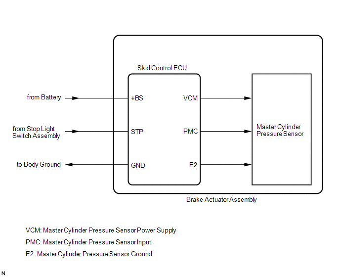
The master cylinder pressure sensor is connected to the skid control ECU in the brake actuator assembly.
|
DTC No. |
Detection Item |
DTC Detection Condition |
Trouble Area |
|---|---|---|---|
|
C1246 |
Master Cylinder Pressure Sensor Malfunction |
Any of the following is detected:
|
|
|
Vehicle Condition |
||||
|---|---|---|---|---|
|
Pattern 1 |
Pattern 2 |
Pattern 3 |
||
|
Diagnosis Condition |
- |
- |
- |
- |
|
Malfunction Status |
The voltage of the sensor signal is out of range (below 0.129 V, above 3.29 V). |
○ |
- |
- |
|
An abnormality is detected in the skid control ECU internal sensor test. |
- |
○ |
- |
|
|
The sensor signal offset value is out of range. |
- |
- |
○ |
|
|
Detection Time |
- |
- |
- |
|
|
Number of Trips |
1 trip |
1 trip |
1 trip |
|
HINT:
DTC will be output when conditions for either of the patterns in the table above are met.
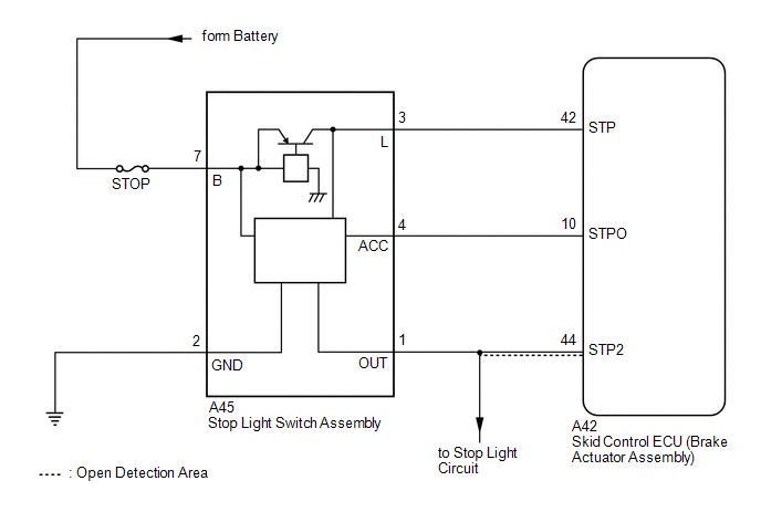
WIRING DIAGRAM
CAUTION / NOTICE / HINT
NOTICE:
When replacing the skid control ECU (brake actuator assembly), perform system variant learning.
Click here
.gif)
PROCEDURE
|
1. |
CHECK STOP LIGHT OPERATION |
(a) Check that the stop lights come on when the brake pedal is depressed, and go off when the brake pedal is released.
OK:
|
Condition |
Illumination Condition |
|---|---|
|
Brake pedal depressed. |
On |
|
Brake pedal released. |
Off |
| NG | .gif) |
INSPECT LIGHTING SYSTEM (STOP LIGHT CIRCUIT)
|
|
.gif)
|
2. |
READ VALUE USING TECHSTREAM (MASTER CYLINDER PRESSURE SENSOR) |
(a) Connect the Techstream to the DLC3.
(b) Start the engine.
(c) Select the Data List using the Techstream.
Click here
|
Tester Display |
Measurement Item |
Range |
Normal Condition |
Diagnostic Note |
|---|---|---|---|---|
|
Master Cylinder Sensor |
Master cylinder pressure sensor reading |
Min.: 0.00 V, Max.: 5.00 V |
When brake pedal released: 0.2 to 0.4 V |
Reading increases when brake pedal is depressed |
|
Tester Display |
|---|
|
Master Cylinder Sensor |
(d) Check that the brake fluid pressure value of the master cylinder pressure sensor observed on the Techstream changes when the brake pedal is depressed.
OK:
When the pedal is depressed, the voltage displayed on the Techstream increases.
| NG | |
REPLACE BRAKE ACTUATOR ASSEMBLY |
|
|
3. |
READ VALUE USING TECHSTREAM (STOP LIGHT SWITCH ASSEMBLY) |
(a) Connect the Techstream to the DLC3.
(b) Turn the ignition switch to ON.
(c) Select the Data List using the Techstream.
Click here
|
Tester Display |
Measurement Item |
Range |
Normal Condition |
Diagnostic Note |
|---|---|---|---|---|
|
Stop Light SW |
Stop light switch |
ON or OFF |
ON: Brake pedal depressed OFF: Brake pedal released |
- |
|
Tester Display |
|---|
|
Stop Light SW |
(d) Check that the stop light switch display observed on the Techstream changes according to brake pedal operation.
OK:
The Techstream displays ON or OFF according to brake pedal operation.
| NG | |
GO TO STEP 5 |
|
|
4. |
RECONFIRM DTC |
(a) Turn the ignition switch off.
(b) Clear the DTCs.
Click here
(c) Turn the ignition switch off.
(d) Start the engine.
(e) Drive the vehicle and depress the brake pedal several times to test the stop light circuit.
(f) Check if the same DTC is output.
Click here
|
Result |
Proceed to |
|---|---|
|
DTC C1246 is not output. |
A |
|
DTC C1246 is output. |
B |
HINT:
If troubleshooting has been carried out according to Problem Symptoms Table, refer back to the table and proceed to the next step before replacing parts.
Click here
| A | |
USE SIMULATION METHOD TO CHECK
|
| B | |
REPLACE BRAKE ACTUATOR ASSEMBLY |
|
5. |
CHECK HARNESS AND CONNECTOR (STP TERMINAL) |
|
(a) Turn the ignition switch off. |
|
(b) Make sure that there is no looseness at the locking part and the connecting part of the connector.
(c) Disconnect the A42 skid control ECU (brake actuator assembly) connector.
(d) Measure the voltage according to the value(s) in the table below.
Standard Voltage:
|
Tester Connection |
Condition |
Specified Condition |
|---|---|---|
|
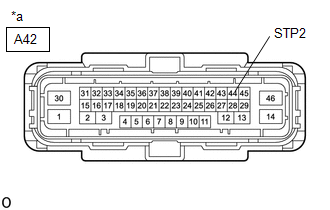
A42-44 (STP2) - Body ground |
Stop light switch ON (Brake pedal depressed) |
11 to 14 V* |
|
A42-44 (STP2) - Body ground |
Stop light switch OFF (Brake pedal released) |
Below 1.5 V |
HINT:
*: The standard voltage value varies depending on the +BS terminal voltage value. The standard voltage is 85% of the +BS terminal voltage.
HINT:
If troubleshooting has been carried out according to Problem Symptoms Table, refer back to the table and proceed to the next step before replacing parts.
Click here
| OK | |
REPLACE BRAKE ACTUATOR ASSEMBLY |
| NG | |
REPAIR OR REPLACE HARNESS OR CONNECTOR (STP CIRCUIT) |
 Acceleration Sensor Stuck Malfunction (C1243,C1245)
DESCRIPTION
The skid control ECU (brake actuator assembly) receives signals from the yaw
rate and acceleration sensor (airbag sensor assembly) via CAN communication.
The airbag sensor assembly has ...
 Open in Stop Light Switch Circuit (C1249)
DESCRIPTION
The skid control ECU (brake actuator assembly) receives stop light switch signals
and uses them to determine whether or not the brakes are applied. DTCs may be stored
if either of the ...
Other materials:
Toyota CH-R Service Manual > Audio And Visual System(for Radio And Display Type): Vehicle Speed Signal Circuit between Radio Receiver and Combination Meter
DESCRIPTION
for Automatic Sound Levelizer (ASL):
This circuit is necessary for the Automatic Sound Levelizer (ASL) built
into the radio and display receiver assembly.
The Automatic Sound Levelizer (ASL) function automatically adjusts the
audio system volume level in order to com ...
Toyota CH-R Service Manual > Headlight Assembly(for Halogen Headlight): Disassembly
DISASSEMBLY
CAUTION / NOTICE / HINT
HINT:
Use the same procedure for the RH side and LH side.
The following procedure is for the LH side.
PROCEDURE
1. REMOVE HEADLIGHT PROTECTOR
(a) Remove the headlight protector.
2. ...
Toyota C-HR (AX20) 2023-2026 Owner's Manual
Toyota CH-R Owners Manual
- For safety and security
- Instrument cluster
- Operation of each component
- Driving
- Interior features
- Maintenance and care
- When trouble arises
- Vehicle specifications
- For owners
Toyota CH-R Service Manual
- Introduction
- Maintenance
- Audio / Video
- Cellular Communication
- Navigation / Multi Info Display
- Park Assist / Monitoring
- Brake (front)
- Brake (rear)
- Brake Control / Dynamic Control Systems
- Brake System (other)
- Parking Brake
- Axle And Differential
- Drive Shaft / Propeller Shaft
- K114 Cvt
- 3zr-fae Battery / Charging
- Networking
- Power Distribution
- Power Assist Systems
- Steering Column
- Steering Gear / Linkage
- Alignment / Handling Diagnosis
- Front Suspension
- Rear Suspension
- Tire / Wheel
- Tire Pressure Monitoring
- Door / Hatch
- Exterior Panels / Trim
- Horn
- Lighting (ext)
- Mirror (ext)
- Window / Glass
- Wiper / Washer
- Door Lock
- Heating / Air Conditioning
- Interior Panels / Trim
- Lighting (int)
- Meter / Gauge / Display
- Mirror (int)
- Power Outlets (int)
- Pre-collision
- Seat
- Seat Belt
- Supplemental Restraint Systems
- Theft Deterrent / Keyless Entry

0.0087