Toyota CH-R Service Manual: Inspection
INSPECTION
PROCEDURE
1. INSPECT BRAKE CYLINDER AND PISTON
(a) Check the front disc brake cylinder bore and front disc brake piston for rust and scoring. If necessary, replace the front disc brake cylinder assembly and front disc brake piston.
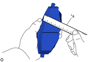
2. INSPECT PAD LINING THICKNESS
|
(a) Using a ruler, measure the front disc brake pad lining thickness. Standard Thickness: 12.2 mm (0.480 in.) Minimum Thickness: 1.0 mm (0.0394 in.) HINT:
|
|
3. INSPECT FRONT DISC BRAKE PAD SUPPORT PLATE
(a) Make sure that the front disc brake pad support plates have sufficient rebound, no deformation, cracks or wear, and that all rust and dirt is cleaned off. If necessary, replace the front disc brake pad support plates.
(b) Before installing the front disc brake pad support plates on the front disc brake cylinder mounting, clean the installation surface of the brake cylinder mounting with brake cleaner.
(c) Install the front disc brake pad support plates, and check that there is no looseness or deformation.
(d) Before installing the front disc brake pads, check that the brake pad support plates have spring force.
(e) Install the brake pads, and check that they do not come off easily.
4. INSPECT DISC THICKNESS
|
(a) Using a micrometer, measure the front disc thickness. Standard Thickness: 28.0 mm (1.10 in.) Minimum Thickness: 25 mm (0.984 in.) HINT: If the front disc thickness is less than the minimum thickness, replace the front disc. |
|
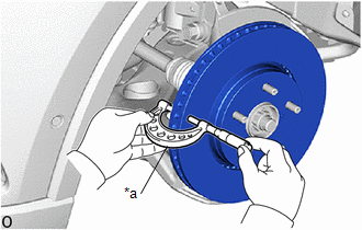
5. INSPECT DISC RUNOUT
(a) Inspect the front axle hub bearing looseness and front axle hub runout.
Click here
.gif)
(b) Align the matchmarks of the front disc and front axle hub, and temporarily install the front disc with the 5 hub nuts.
Torque:
103 N·m {1050 kgf·cm, 76 ft·lbf}
|
(c) Using a dial indicator, measure the disc runout 10 mm (0.394 in.) from the outer edge of the front disc. Maximum Disc Runout: 0.05 mm (0.00196 in.) NOTICE: Keep the magnet of the dial indicator away from the front speed sensor. HINT: If the runout exceeds the maximum value, change the installation position of the front disc to minimize the runout. If the runout exceeds the maximum even when the installation position is changed, grind the front disc. If the front disc thickness is less than the minimum, replace the front disc. |
|

(d) Remove the 5 hub nuts and front disc.
 Disassembly
DISASSEMBLY
PROCEDURE
1. REMOVE FRONT DISC BRAKE PISTON
(a) Place a piece of cloth between the front disc brake piston and front
disc brake cylinder assembly.
...
 Reassembly
REASSEMBLY
PROCEDURE
1. TEMPORARILY TIGHTEN FRONT DISC BRAKE BLEEDER PLUG
(a) Temporarily install the front disc brake bleeder plug to the front disc brake
cylinder assembly.
HINT:
Fully tighte ...
Other materials:
Toyota CH-R Service Manual > Power Window Control System: How To Proceed With Troubleshooting
CAUTION / NOTICE / HINT
HINT:
Use the following procedure to troubleshoot the power window control
system.
*: Use the Techstream.
PROCEDURE
1.
VEHICLE BROUGHT TO WORKSHOP
NEXT
...
Toyota CH-R Owners Manual > Steps to take in an emergency: If the vehicle becomes stuck
Carry out the following procedures if the tires spin or the vehicle
becomes stuck in mud, dirt or snow:
Stop the engine. Shift the shift lever to P, and set the parking brake.
Remove the mud, snow or sand from around the front wheels.
Place wood, stones or some other material under the fro ...
Toyota C-HR (AX20) 2023-2026 Owner's Manual
Toyota CH-R Owners Manual
- For safety and security
- Instrument cluster
- Operation of each component
- Driving
- Interior features
- Maintenance and care
- When trouble arises
- Vehicle specifications
- For owners
Toyota CH-R Service Manual
- Introduction
- Maintenance
- Audio / Video
- Cellular Communication
- Navigation / Multi Info Display
- Park Assist / Monitoring
- Brake (front)
- Brake (rear)
- Brake Control / Dynamic Control Systems
- Brake System (other)
- Parking Brake
- Axle And Differential
- Drive Shaft / Propeller Shaft
- K114 Cvt
- 3zr-fae Battery / Charging
- Networking
- Power Distribution
- Power Assist Systems
- Steering Column
- Steering Gear / Linkage
- Alignment / Handling Diagnosis
- Front Suspension
- Rear Suspension
- Tire / Wheel
- Tire Pressure Monitoring
- Door / Hatch
- Exterior Panels / Trim
- Horn
- Lighting (ext)
- Mirror (ext)
- Window / Glass
- Wiper / Washer
- Door Lock
- Heating / Air Conditioning
- Interior Panels / Trim
- Lighting (int)
- Meter / Gauge / Display
- Mirror (int)
- Power Outlets (int)
- Pre-collision
- Seat
- Seat Belt
- Supplemental Restraint Systems
- Theft Deterrent / Keyless Entry

0.008