Toyota CH-R Service Manual: Power Source Circuit
DESCRIPTION
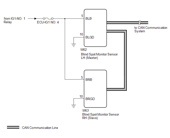
This circuit provides power to operate the blind spot monitor sensor.
WIRING DIAGRAM
CAUTION / NOTICE / HINT
NOTICE:
Inspect the fuses for circuits related to this system before performing the following procedure.
PROCEDURE
|
1. |
CHECK HARNESS AND CONNECTOR (BLIND SPOT MONITOR SENSOR LH (MASTER) POWER SOURCE) |
|
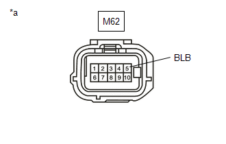
*a |
Front view of wire harness connector (to blind spot monitor sensor LH (Master)) |
(a) Disconnect the blind spot monitor sensor LH (Master) connector.
(b) Measure the voltage according to the value(s) in the table below.
Standard Voltage:
|
Tester Connection |
Switch Condition |
Specified Condition |
|---|---|---|
|
M62-5 (BLB) - Body ground |
Ignition switch to ON |
11 to 14 V |
|
M62-5 (BLB) - Body ground |
Ignition switch off |
Below 1 V |
| NG | .gif) |
REPAIR OR REPLACE HARNESS OR CONNECTOR |
|
.gif)
|
2. |
CHECK HARNESS AND CONNECTOR (BLIND SPOT MONITOR SENSOR LH (MASTER) - BODY GROUND) |
(a) Measure the resistance according to the value(s) in the table below.
Standard Resistance:
|
Tester Connection |
Condition |
Specified Condition |
|---|---|---|
|
M62-10 (BLGD) - Body ground |
Always |
Below 1 Ω |
| NG | |
REPAIR OR REPLACE HARNESS OR CONNECTOR |
|
|
3. |
CHECK HARNESS AND CONNECTOR (BLIND SPOT MONITOR SENSOR RH (SLAVE) POWER SOURCE) |
|
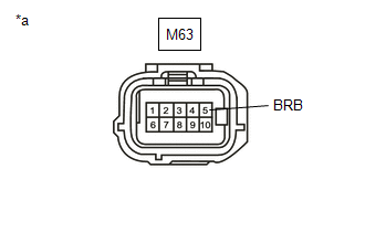
*a |
Front view of wire harness connector (to blind spot monitor sensor RH(Slave)) |
(a) Disconnect the blind spot monitor sensor RH (Slave) connector.
(b) Measure the voltage according to the value(s) in the table below.
Standard Voltage:
|
Tester Connection |
Switch Condition |
Specified Condition |
|---|---|---|
|
M63-5 (BRB) - Body ground |
Ignition switch to ON |
11 to 14 V |
|
M63-5 (BRB) - Body ground |
Ignition switch off |
Below 1 V |
| NG | |
REPAIR OR REPLACE HARNESS OR CONNECTOR |
|
|
4. |
CHECK HARNESS AND CONNECTOR (BLIND SPOT MONITOR SENSOR RH (SLAVE) - BODY GROUND) |
(a) Measure the resistance according to the value(s) in the table below.
Standard Resistance:
|
Tester Connection |
Condition |
Specified Condition |
|---|---|---|
|
M63-10 (BRGD) - Body ground |
Always |
Below 1 Ω |
| OK | |
PROCEED TO NEXT SUSPECTED AREA SHOWN IN PROBLEM SYMPTOMS TABLE |
| NG | |
REPAIR OR REPLACE HARNESS OR CONNECTOR |
 Yaw Rate Sensor (C1A46)
DESCRIPTION
The blind spot monitor sensor receives yaw rate signals from the airbag sensor
assembly via CAN communication.
DTC No.
Detection Item
DTC Detection Con ...

Other materials:
Toyota CH-R Service Manual > Meter / Gauge System: Tachometer Malfunction
DESCRIPTION
In this circuit, the combination meter assembly receives engine speed signals
from the ECM via CAN communication. The combination meter assembly displays the
engine speed calculated based on the data received from the ECM.
WIRING DIAGRAM
CAUTION / NOTICE / HINT
NOTICE:
...
Toyota CH-R Owners Manual > Operating the lights and wipers: Rear window wiper and washer
Operating instructions
Turning the
switch
turns on the rear window wiper and washer as follows:
OFF *1 or
*2
Off
INT *1 or
*2
Intermittent window wiper operation
ON *1 or
*2
Normal window wiper operation
*1: For U.S.A.
*2: For Canada
Washer/wiper dual operation ...
Toyota C-HR (AX20) 2023-2026 Owner's Manual
Toyota CH-R Owners Manual
- For safety and security
- Instrument cluster
- Operation of each component
- Driving
- Interior features
- Maintenance and care
- When trouble arises
- Vehicle specifications
- For owners
Toyota CH-R Service Manual
- Introduction
- Maintenance
- Audio / Video
- Cellular Communication
- Navigation / Multi Info Display
- Park Assist / Monitoring
- Brake (front)
- Brake (rear)
- Brake Control / Dynamic Control Systems
- Brake System (other)
- Parking Brake
- Axle And Differential
- Drive Shaft / Propeller Shaft
- K114 Cvt
- 3zr-fae Battery / Charging
- Networking
- Power Distribution
- Power Assist Systems
- Steering Column
- Steering Gear / Linkage
- Alignment / Handling Diagnosis
- Front Suspension
- Rear Suspension
- Tire / Wheel
- Tire Pressure Monitoring
- Door / Hatch
- Exterior Panels / Trim
- Horn
- Lighting (ext)
- Mirror (ext)
- Window / Glass
- Wiper / Washer
- Door Lock
- Heating / Air Conditioning
- Interior Panels / Trim
- Lighting (int)
- Meter / Gauge / Display
- Mirror (int)
- Power Outlets (int)
- Pre-collision
- Seat
- Seat Belt
- Supplemental Restraint Systems
- Theft Deterrent / Keyless Entry

0.0073