Toyota CH-R Service Manual: Operation Check
OPERATION CHECK
HINT:
The blind spot monitor beam axis confirmation is performed to confirm whether the sensor's beam axis is correct, and perform adjustment of the beam axis by using reflector.
BLIND SPOT MONITOR BEAM AXIS CONFIRMATION
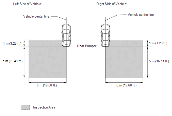
(a) When performing the blind spot monitor beam axis confirmation, move the vehicle to a place where the space shown in the illustration can be secured.
NOTICE:
- Perform this inspection on level ground.
- Make sure that there are no metal objects around the vehicle or on the ground.
- Unload the vehicle before beginning the inspection.
- Confirm that the tire pressure is correct before beginning the inspection.
- Do not place any objects other than the reflector (such as a large metallic object) in or allow people to enter the inspection area (W 6 m (19.68 ft.) x L 6 m (19.68 ft.) x H 4 m (13.12 ft.)) shown in the illustration.
(b) Place the reflector.
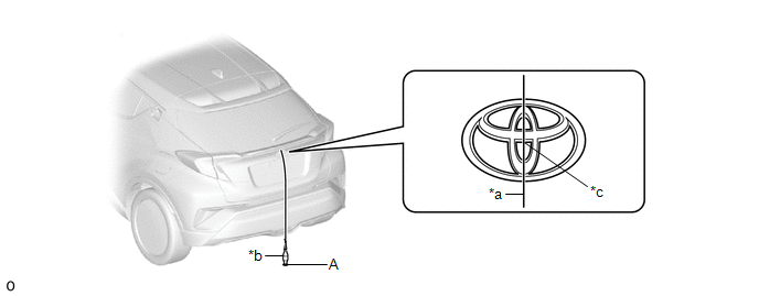
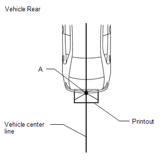
(1) From the center of the rear bumper (center of the emblem), hang a weight with a pointed tip, and mark the rear center point of the vehicle on the ground (mark A).
|
*a |
String |
*b |
Weight |
|
*c |
Center point |
- |
- |
HINT:
Lightly flick the string with your fingers several times to confirm that the string is aligned with mark A.
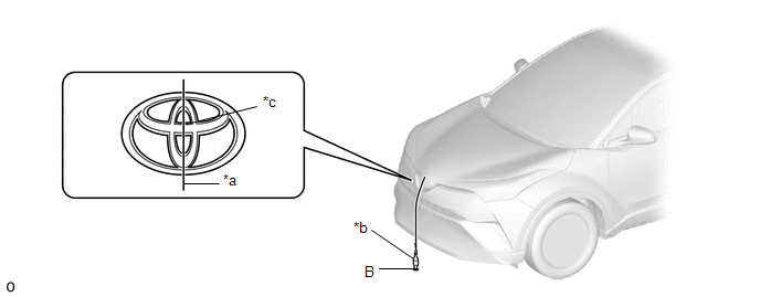
(2) From the center of the front bumper (center of the emblem), hang a weight with a pointed tip, and mark the front center point of the vehicle on the ground (mark B).
|
*a |
String |
*b |
Weight |
|
*c |
Center point |
- |
- |
HINT:
Lightly flick the string with your fingers several times to confirm that the string is aligned with mark (B).
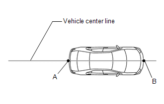
(3) Draw a vehicle center line so that it passes through mark (A) and (B) (front and rear center points).
(4) Print out the following illustration on a large piece of paper.
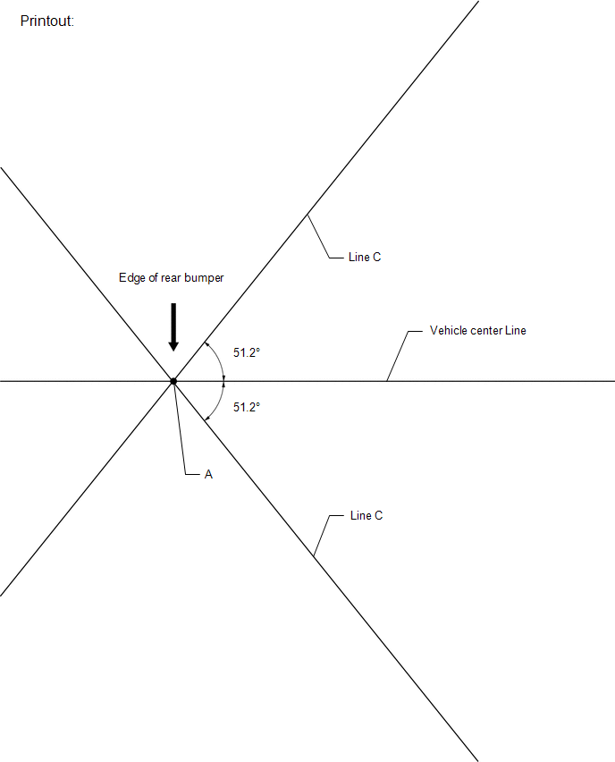
(5) Place the printout on the floor with the point A aligned with the longitudinal center line of the vehicle.
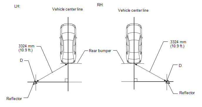
(6) Align a piece of string with line C and mark point D at a distance of 3324 mm (10.9 ft.) from point A.
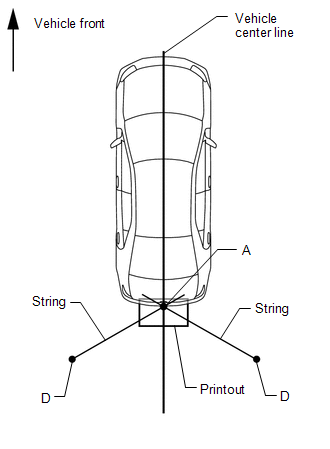
(7) Set the reflector at the point D shown in the illustration below.
SST: 09870-60000
09870-60010
SST: 09870-60040
NOTICE:
- Set the reflector so that its center is 797 mm (2.61 ft.) above the
ground.
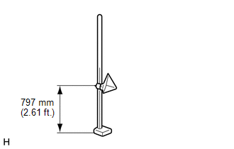
- The center of the triangular pyramid is the reference point for the
setting position and angle.
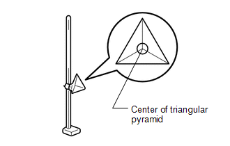
- Set the reflector as shown in the illustration so that the center of the triangular pyramid faces the blind spot monitor sensor.
(c) Perform the blind spot monitor beam axis display.
(1) Connect the Techstream to the DLC3.
(2) Turn the ignition switch to ON.
(3) Turn the blind spot monitor system on.
(4) Turn the Techstream on.
(5) Enter the following menus: Body Electrical / Blind Spot Monitor Master or Blind Spot Monitor Slave / Utility / BSM Master Beam Axis Display or BSM Slave Beam Axis Display.
Body Electrical > Blind Spot Monitor Master > Utility|
Tester Display |
|---|
|
BSM Master Beam Axis Display |
|
Tester Display |
|---|
|
BSM Slave Beam Axis Display |
(6) Check the results displayed for the BSM beam axis display.
Allowable Range:
|
Item |
Blind Spot Monitor Sensor LH (Master) |
Blind Spot Monitor Sensor RH (Slave) |
|---|---|---|
|
Angle |
-3.55 to +3.55° |
-3.55 to +3.55° |
HINT:
If the results are outside the allowable range, it is possible that the reflector position is incorrect, there is a metallic object near the inspection area or the blind spot monitor sensor installation condition is abnormal, so check the reflector positioning, the inspection area and the blind spot monitor sensor installation condition, and perform the inspection again.
(d) Perform the blind spot monitor beam axis adjustment.
(1) Enter the following menus: Body Electrical / Blind Spot Monitor Master or Blind Spot Monitor Slave / Utility / BSM Master Beam Axis Adjustment or BSM Slave Beam Axis Adjustment.
HINT:
When values on the axis display are in the allowable range, performing this adjustment compensates for any deviation from the normal value.
Body Electrical > Blind Spot Monitor Master > Utility|
Tester Display |
|---|
|
BSM Master Beam Axis Adjustment |
|
Tester Display |
|---|
|
BSM Slave Beam Axis Adjustment |
BLIND SPOT MONITOR SENSOR INSTALLATION CONDITION INSPECTION
NOTICE:
- Perform this inspection on level ground.
- Unload the vehicle before beginning the inspection.
- Confirm that the tire pressure is correct before beginning the inspection.
HINT:
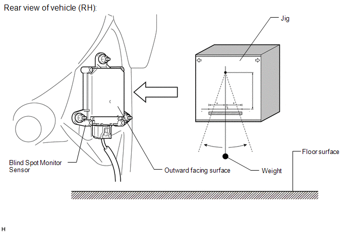
The blind spot monitor sensor installation condition inspection is performed to confirm whether the sensor is perpendicular to the floor surface (+/-3°) by using a jig, and that the sensor is 46 to 54° from the line parallel to the vehicle center line.
(a) Remove the rear bumper.
Click here
.gif)
(b) Attach a jig similar to the one shown in the illustration to the outward facing surface of the blind spot monitor sensor and check that the measurement or angle is within the allowable range to confirm that the blind spot monitor sensor is perpendicular to the floor surface (+/-3°).
HINT:
A digital angle meter can also be used to check that the blind spot monitor sensor is perpendicular to the floor surface or within the allowable range.
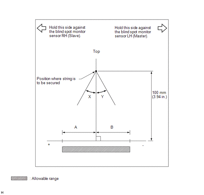 Standard
|
A |
B |
|
|---|---|---|
|
Blind spot monitor sensor LH (Master) |
5.2 mm (0.206 in.) |
-5.2 mm (-0.206 in.) |
|
Blind spot monitor sensor RH (Slave) |
5.2 mm (0.206 in.) |
-5.2 mm (-0.206 in.) |
|
X |
Y |
|
|---|---|---|
|
Blind spot monitor sensor LH (Master) |
3° |
-3° |
|
Blind spot monitor sensor RH (Slave) |
3° |
-3° |
(c) Using the sensor installation stud bolt center lines as a reference, check that the stud bolts are as shown in the illustration.
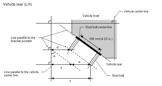
Standard:
|
Dimension x - w |
Specified Value |
|---|---|
|
y |
78 to 87 mm (3.07 to 3.43 in.) |
|
Degree |
Specified Value |
|---|---|
|
A |
46 to 54° |
HINT:
If the results are not as specified, it is possible that the blind spot monitor sensor installation area (frame, stud bolt) is deformed, so make corrections as necessary.
 System Description
SYSTEM DESCRIPTION
GENERAL
(a) The blind spot monitor system has a blind spot monitor function and RCTA
function.
(1) Blind spot monitor function
The blind spot monitor function is a func ...
 Customize Parameters
CUSTOMIZE PARAMETERS
CUSTOMIZE BLIND SPOT MONITOR SYSTEM
(a) Customizing with the Techstream
NOTICE:
When the customer requests a change in a function, first make sure that
the functio ...
Other materials:
Toyota CH-R Service Manual > Automatic High Beam System: Automatic High Beam Camera (B124C)
DESCRIPTION
This DTC is stored when the main body ECU (multiplex network body ECU) detects
a malfunction in the forward recognition camera.
DTC No.
Detection Item
DTC Detection Condition
Trouble Area
B124C
Automatic High Bea ...
Toyota CH-R Service Manual > Rear Shock Absorber: Components
COMPONENTS
ILLUSTRATION
*1
REAR SHOCK ABSORBER ASSEMBLY
*2
REAR STABILIZER LINK ASSEMBLY
*3
REAR UPPER CONTROL ARM ASSEMBLY
*4
REAR STABILIZER BAR
Tightening torque for "M ...
Toyota C-HR (AX20) 2023-2026 Owner's Manual
Toyota CH-R Owners Manual
- For safety and security
- Instrument cluster
- Operation of each component
- Driving
- Interior features
- Maintenance and care
- When trouble arises
- Vehicle specifications
- For owners
Toyota CH-R Service Manual
- Introduction
- Maintenance
- Audio / Video
- Cellular Communication
- Navigation / Multi Info Display
- Park Assist / Monitoring
- Brake (front)
- Brake (rear)
- Brake Control / Dynamic Control Systems
- Brake System (other)
- Parking Brake
- Axle And Differential
- Drive Shaft / Propeller Shaft
- K114 Cvt
- 3zr-fae Battery / Charging
- Networking
- Power Distribution
- Power Assist Systems
- Steering Column
- Steering Gear / Linkage
- Alignment / Handling Diagnosis
- Front Suspension
- Rear Suspension
- Tire / Wheel
- Tire Pressure Monitoring
- Door / Hatch
- Exterior Panels / Trim
- Horn
- Lighting (ext)
- Mirror (ext)
- Window / Glass
- Wiper / Washer
- Door Lock
- Heating / Air Conditioning
- Interior Panels / Trim
- Lighting (int)
- Meter / Gauge / Display
- Mirror (int)
- Power Outlets (int)
- Pre-collision
- Seat
- Seat Belt
- Supplemental Restraint Systems
- Theft Deterrent / Keyless Entry

0.008