Toyota CH-R Service Manual: System Description
SYSTEM DESCRIPTION
GENERAL
(a) The blind spot monitor system has a blind spot monitor function and RCTA function.
(1) Blind spot monitor function
- The blind spot monitor function is a function that assists the driver
when changing lanes.
This function uses quasi-millimeter wave radar to detect vehicles that are traveling in adjacent lanes in the areas that are not visible using the outer rear view mirror assemblies (blind spots) and vehicles that are approaching rapidly from up to 60 m behind this vehicle in the areas that are not visible using the outer rear view mirror assemblies (blind spots).
The function advises the driver of the existence of a vehicle by illuminating the outer rear view mirror indicator on the outer rear view mirror assembly.
- If the turn signal switch is operated while the outer rear view mirror indicator on an outer rear view mirror assembly is illuminated, the indicator starts blinking to give additional warning to the driver.
(2) RCTA function
- The RCTA function is a function that informs the driver a vehicle is approaching from the left or the right at the rear of the vehicle. The function uses quasi-millimeter wave radar to detect the position and relative speed of other vehicles. When the function determines that a vehicle is approaching this vehicle, this function informs the driver using the outer rear view mirror indicators and blind spot monitor buzzer.
FUNCTION OF COMPONENTS
|
Component |
Function |
|---|---|
|
Blind Spot Monitor Sensor |
|
|
Outer Rear View Mirror Assembly
|
Turns on or blinks the indicator based on a signal from the blind spot monitor sensor. |
|
Steering Pad Switch Assembly |
|
|
RCTA Buzzer (Blind Spot Monitor Buzzer) |
Sounds based on a signal from the blind spot monitor sensor. |
|
Combination Meter Assembly
|
|
|
Main Body ECU (Multiplex Network Body ECU) |
Transmits the destination information and the dimmer signal to the blind spot monitor sensor via CAN communication. |
|
Skid Control ECU |
Transmits the vehicle speed signal to the blind spot monitor sensor via CAN communication. |
|
ECM |
Transmits the shift position signal (R) to the blind spot monitor sensor via CAN communication. |
|
Steering Sensor |
Detects the angle of the steering wheel and transmits the resulting signals to the blind spot monitor sensor via CAN communication. |
|
Airbag Sensor Assembly |
Transmits the yaw rate signal to the blind spot monitor sensor via CAN communication. |
OPERATION DESCRIPTION
(a) Operation description of the blind spot monitor function
(1) Operation conditions:
- The blind spot monitor system is on.
- The shift lever is in any position other than R.
- Vehicle speed is more than approximately 16 km/h (10 mph).
(2) Conditions in which a sensor can detect a vehicle
The blind spot monitor function indicates detection of a vehicle in the detection area when either condition is met:
- When a vehicle is detected in an adjacent lane overtaking this vehicle.
- When a vehicle is detected entering the detection area because it changed lanes.
HINT:
The greater the difference in speed between the vehicle and the detected vehicle is, the farther away the other vehicle will be when the notification is given.
(3) Detection area
Vehicles in the following areas can be detected:
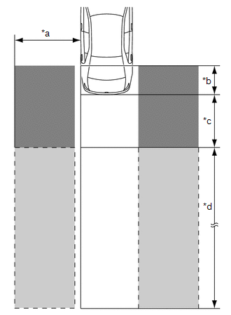
|
*a |
Within Approximately. 3.5 m (11.48 ft.) from Side of Vehicle |
|
*b |
Within Approximately. 1 m (3.28 ft.) Forward of Rear Bumper |
|
*c |
Within Approximately. 3 m (9.84 ft.) Behind Rear Bumper |
|
*d |
Within Approximately. 3 m (9.84 ft.) to 60 m (196.86 ft.) from Rear Bumper |
.png)
|
Detection Area (for Vehicle in Blind Spot) |
 |
Detection Area (for Rapidly Approaching Vehicle from Behind) |
(b) Operation description of the RCTA function
(1) Operation conditions:
- The blind spot monitor system is on.
- The shift lever is in R.
- The vehicle speed is less than approximately 8 km/h (5 mph).
(2) Conditions in which a sensor can detect a vehicle
The RCTA function indicates detection of a vehicle in the detection area when both conditions are met:
- A vehicle is approaching from the right or left at the rear of the vehicle.
- The vehicle speed is approximately 8 km/h (5 mph) to 28 km/h (17 mph).
(3) Detection area
Vehicles in the following areas can be detected:
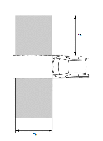
|
*a |
Within Approximately. 5.5 to 20 m (18.05 to 65.62 ft.) from Side of Vehicle (detection area changes according to vehicle speed) |
|
*b |
Within Approximately. 6 m (19.69 ft.) Behind Rear Bumper |
|
|
Detection Area |
HINT:
"RCTA system" must be equipped with "Rear view monitor", because "Blind Spot Monitor Sensor" cannot detect a vehicle right behind.
OPERATION OF OUTER REAR VIEW MIRROR INDICATOR AND RCTA BUZZER (BLIND SPOT MONITOR BUZZER)
(a) Initial check
(1) When the blind spot monitor system is turned on with the ignition switch to ON, the outer rear view mirror indicators on the outer rear view mirror assembly illuminate for 3 seconds and the RCTA buzzer (blind spot monitor buzzer) sounds for 1 second.
(2) When the ignition switch is turned from off to ON with the blind spot monitor system on, the outer rear view mirror indicators on the outer rear view mirror assembly illuminate for 3 seconds.
(b) Operation for each function
(1) Operation for blind spot monitor function
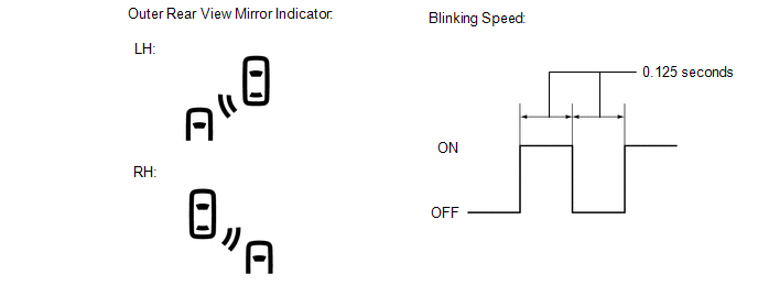
- When a sensor detects a vehicle in the blind spot area or a vehicle is rapidly approaching the blind spot from behind the vehicle, the outer rear view mirror indicator on the outer rear view mirror assembly illuminates.
- If the turn signal switch is operated, while the sensor is detecting a vehicle in the detection area and the outer rear view mirror indicator on the outer rear view mirror assembly is illuminated, the indicator starts blinking as shown in the illustration.
(2) Operation for RCTA function
- When all of the operation conditions for the RCTA function are met, the outer rear view mirror indicators on the outer rear view mirror assembly blink for 2.5 seconds and the RCTA buzzer (blind spot monitor buzzer) sounds for 2.3 seconds as shown in the illustration.
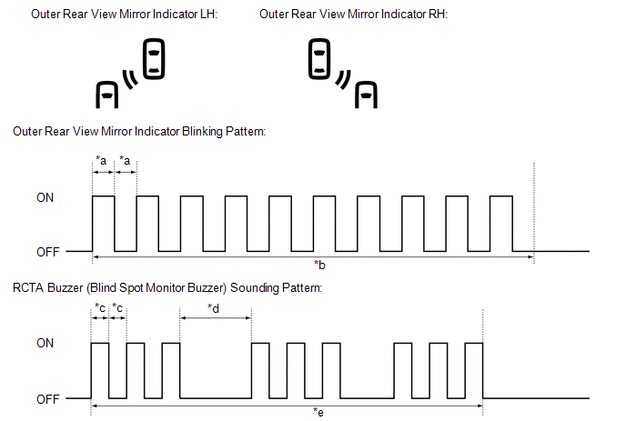
|
*a |
0.125 Seconds |
*b |
2.5 Seconds |
|
*c |
0.1 Seconds |
*d |
0.4 Seconds |
|
*e |
2.3 Seconds |
- |
- |
 How To Proceed With Troubleshooting
CAUTION / NOTICE / HINT
HINT:
Use the following procedure to troubleshoot the blind spot monitor system.
*: Use the Techstream.
PROCEDURE
1.
VEHICLE BRO ...
 Operation Check
OPERATION CHECK
HINT:
The blind spot monitor beam axis confirmation is performed to confirm whether
the sensor's beam axis is correct, and perform adjustment of the beam axis by using
reflec ...
Other materials:
Toyota CH-R Service Manual > Key Reminder Warning System: Parts Location
PARTS LOCATION
ILLUSTRATION
*1
FRONT DOOR COURTESY LIGHT SWITCH ASSEMBLY (for LH)
*2
UNLOCK WARNING SWITCH ASSEMBLY
*3
COMBINATION METER ASSEMBLY
*4
DLC3
*5
MAIN BODY ECU (MU ...
Toyota CH-R Service Manual > Electric Parking Brake System: EPB High Temperature (C13AA)
DESCRIPTION
If the electric parking brake is used continuously, system operation is stopped
to prevent the parking brake actuator assembly from overheating.
This DTC is stored when system operation is stopped to prevent the parking brake
actuator assembly from overheating and is not a malfunct ...
Toyota C-HR (AX20) 2023-2026 Owner's Manual
Toyota CH-R Owners Manual
- For safety and security
- Instrument cluster
- Operation of each component
- Driving
- Interior features
- Maintenance and care
- When trouble arises
- Vehicle specifications
- For owners
Toyota CH-R Service Manual
- Introduction
- Maintenance
- Audio / Video
- Cellular Communication
- Navigation / Multi Info Display
- Park Assist / Monitoring
- Brake (front)
- Brake (rear)
- Brake Control / Dynamic Control Systems
- Brake System (other)
- Parking Brake
- Axle And Differential
- Drive Shaft / Propeller Shaft
- K114 Cvt
- 3zr-fae Battery / Charging
- Networking
- Power Distribution
- Power Assist Systems
- Steering Column
- Steering Gear / Linkage
- Alignment / Handling Diagnosis
- Front Suspension
- Rear Suspension
- Tire / Wheel
- Tire Pressure Monitoring
- Door / Hatch
- Exterior Panels / Trim
- Horn
- Lighting (ext)
- Mirror (ext)
- Window / Glass
- Wiper / Washer
- Door Lock
- Heating / Air Conditioning
- Interior Panels / Trim
- Lighting (int)
- Meter / Gauge / Display
- Mirror (int)
- Power Outlets (int)
- Pre-collision
- Seat
- Seat Belt
- Supplemental Restraint Systems
- Theft Deterrent / Keyless Entry

0.0069