Toyota CH-R Service Manual: IG Power Source Circuit
DESCRIPTION
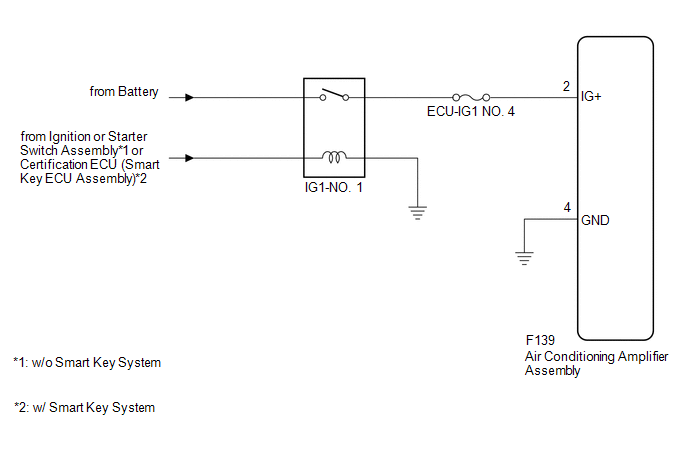
Power source voltage is supplied to the air conditioning amplifier assembly when the ignition switch is turned ON. This power is used for operating the air conditioning amplifier assembly, servo motors, etc.
WIRING DIAGRAM
CAUTION / NOTICE / HINT
NOTICE:
Inspect the fuses for circuits related to this system before performing the following procedure.
PROCEDURE
|
1. |
CHECK HARNESS AND CONNECTOR (AIR CONDITIONING AMPLIFIER ASSEMBLY - IG POWER SOURCE) |
|
(a) Disconnect the air conditioning amplifier assembly connector. |
|
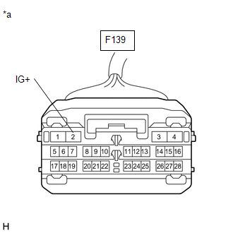
(b) Measure the voltage according to the value(s) in the table below.
Standard Voltage:
|
Tester Connection |
Switch Condition |
Specified Condition |
|---|---|---|
|
F139-2 (IG+) - Body ground |
Ignition switch off |
Below 1 V |
|
F139-2 (IG+) - Body ground |
Ignition switch ON |
11 to 14 V |
| NG | .gif) |
REPAIR OR REPLACE HARNESS OR CONNECTOR |
|
.gif)
|
2. |
CHECK HARNESS AND CONNECTOR (AIR CONDITIONING AMPLIFIER ASSEMBLY - BODY GROUND) |
(a) Measure the resistance according to the value(s) in the table below.
Standard Resistance:
|
Tester Connection |
Condition |
Specified Condition |
|---|---|---|
|
F139-4 (GND) - Body ground |
Always |
Below 1 Ω |
| OK | |
PROCEED TO NEXT SUSPECTED AREA SHOWN IN PROBLEM SYMPTOMS TABLE |
| NG | |
REPAIR OR REPLACE HARNESS OR CONNECTOR |
 Back-up Power Source Circuit
DESCRIPTION
The back-up power source circuit for the air conditioning amplifier assembly
is shown below. Power is supplied even when the ignition switch is off. This power
is used for diagnostic ...

Other materials:
Toyota CH-R Service Manual > Outer Rear View Mirror: Disassembly
DISASSEMBLY
CAUTION / NOTICE / HINT
HINT:
Use the same procedure for the RH side and LH side.
The following procedure is for the LH side.
PROCEDURE
1. REMOVE OUTER MIRROR
Click here
2. REMOVE OUTER MIRROR COVER
Click here
3. REMOVE SIDE TURN SIGNAL LIGHT BULB
Clic ...
Toyota CH-R Service Manual > Rear Door: Components
COMPONENTS
ILLUSTRATION
*1
REAR DOOR BELT REAR SEAL
*2
REAR DOOR BELT SEAL
*3
REAR DOOR GLASS INNER WEATHERSTRIP
*4
REAR DOOR INSIDE HANDLE BEZEL PLUG
*5
REAR DOOR INSIDE HAN ...
Toyota C-HR (AX20) 2023-2026 Owner's Manual
Toyota CH-R Owners Manual
- For safety and security
- Instrument cluster
- Operation of each component
- Driving
- Interior features
- Maintenance and care
- When trouble arises
- Vehicle specifications
- For owners
Toyota CH-R Service Manual
- Introduction
- Maintenance
- Audio / Video
- Cellular Communication
- Navigation / Multi Info Display
- Park Assist / Monitoring
- Brake (front)
- Brake (rear)
- Brake Control / Dynamic Control Systems
- Brake System (other)
- Parking Brake
- Axle And Differential
- Drive Shaft / Propeller Shaft
- K114 Cvt
- 3zr-fae Battery / Charging
- Networking
- Power Distribution
- Power Assist Systems
- Steering Column
- Steering Gear / Linkage
- Alignment / Handling Diagnosis
- Front Suspension
- Rear Suspension
- Tire / Wheel
- Tire Pressure Monitoring
- Door / Hatch
- Exterior Panels / Trim
- Horn
- Lighting (ext)
- Mirror (ext)
- Window / Glass
- Wiper / Washer
- Door Lock
- Heating / Air Conditioning
- Interior Panels / Trim
- Lighting (int)
- Meter / Gauge / Display
- Mirror (int)
- Power Outlets (int)
- Pre-collision
- Seat
- Seat Belt
- Supplemental Restraint Systems
- Theft Deterrent / Keyless Entry

0.0073