Toyota CH-R Service Manual: Voice Guidance does not Function
WIRING DIAGRAM
PROCEDURE
|
1. |
CHECK VOICE GUIDANCE SETTING |
(a) Check that the voice guidance setting is not off.
OK:
Voice guidance setting is not off.
| NG | .gif) |
CHANGE VOICE GUIDANCE SETTING TO ON |
|
.gif)
|
2. |
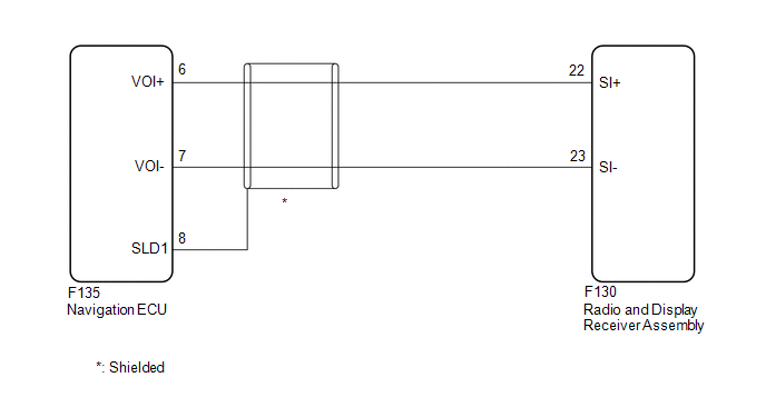
CHECK HARNESS AND CONNECTOR (RADIO AND DISPLAY RECEIVER ASSEMBLY - NAVIGATION ECU) |
(a) Disconnect the F130 radio and display receiver assembly connector.
(b) Disconnect the F135 navigation ECU connector.
(c) Measure the resistance according to the value(s) in the table below.
Standard Resistance:
|
Tester Connection |
Condition |
Specified Condition |
|---|---|---|
|
F130-22 (SI+) - F135-6 (VOI+) |
Always |
Below 1 Ω |
|
F130-23 (SI-) - F135-7 (VOI-) |
Always |
Below 1 Ω |
|
F130-22 (SI+) or F135-6 (VOI+) - Body ground |
Always |
10 kΩ or higher |
|
F130-23 (SI-) or F135-7 (VOI-) - Body ground |
Always |
10 kΩ or higher |
|
F135-8 (SLD1) - Body ground |
Always |
10 kΩ or higher |
| OK | |
PROCEED TO NEXT SUSPECTED AREA SHOWN IN PROBLEM SYMPTOMS TABLE |
| NG | |
REPAIR OR REPLACE HARNESS OR CONNECTOR |
 Cursor or Map Rotates when Vehicle Stopped
PROCEDURE
1.
CHECK CONDITION
(a) Check with the customer if the vehicle has been turned by a turntable.
OK:
Vehicle has not been turned by a turntab ...
 Route cannot be Calculated
PROCEDURE
1.
SET DESTINATION
(a) Set another destination and check if the system can calculate the route correctly.
OK:
Route can be correctly calculated.
...
Other materials:
Toyota CH-R Service Manual > Transmission Control Cable: Installation
INSTALLATION
PROCEDURE
1. INSTALL TRANSMISSION CONTROL CABLE ASSEMBLY
(a) Pass the transmission control cable assembly into the vehicle and
install the transmission control cable assembly to the vehicle body with
the 2 nuts.
Torque:
5.0 N·m {51 kgf·cm, 44 in·lbf}
...
Toyota CH-R Service Manual > Audio And Visual System(for Radio Receiver Type): Portable Player cannot be Connected Manually/Automatically
CAUTION / NOTICE / HINT
HINT:
Some versions of "Bluetooth" compatible audio players may not function properly,
or the functions may be limited using the radio receiver assembly, even if the portable
audio player itself can play files.
Click here
PROCEDURE
1.
...
Toyota C-HR (AX20) 2023-2026 Owner's Manual
Toyota CH-R Owners Manual
- For safety and security
- Instrument cluster
- Operation of each component
- Driving
- Interior features
- Maintenance and care
- When trouble arises
- Vehicle specifications
- For owners
Toyota CH-R Service Manual
- Introduction
- Maintenance
- Audio / Video
- Cellular Communication
- Navigation / Multi Info Display
- Park Assist / Monitoring
- Brake (front)
- Brake (rear)
- Brake Control / Dynamic Control Systems
- Brake System (other)
- Parking Brake
- Axle And Differential
- Drive Shaft / Propeller Shaft
- K114 Cvt
- 3zr-fae Battery / Charging
- Networking
- Power Distribution
- Power Assist Systems
- Steering Column
- Steering Gear / Linkage
- Alignment / Handling Diagnosis
- Front Suspension
- Rear Suspension
- Tire / Wheel
- Tire Pressure Monitoring
- Door / Hatch
- Exterior Panels / Trim
- Horn
- Lighting (ext)
- Mirror (ext)
- Window / Glass
- Wiper / Washer
- Door Lock
- Heating / Air Conditioning
- Interior Panels / Trim
- Lighting (int)
- Meter / Gauge / Display
- Mirror (int)
- Power Outlets (int)
- Pre-collision
- Seat
- Seat Belt
- Supplemental Restraint Systems
- Theft Deterrent / Keyless Entry

0.0095