Toyota CH-R Service Manual: XM Tuner Antenna Disconnected (B15FE,B15FF)
DESCRIPTION
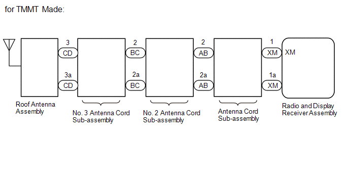
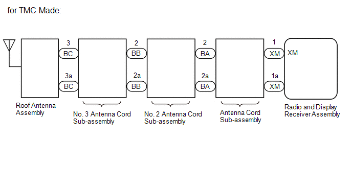
These DTCs are stored when a malfunction occurs in the roof antenna assembly which is connected to the radio and display receiver assembly.
|
DTC No. |
Detection Item |
DTC Detection Condition |
Trouble Area |
|---|---|---|---|
|
B15FE |
XM Tuner Antenna Disconnected |
The roof antenna assembly is not connected |
|
|
B15FF |
XM Tuner Antenna Short |
A short occurs in the roof antenna assembly |
|
WIRING DIAGRAM
CAUTION / NOTICE / HINT
NOTICE:
- Depending on the parts that are replaced during vehicle inspection or
maintenance, performing initialization, registration or calibration may
be needed. Refer to Precaution for Navigation System.
Click here
.gif)
- When replacing the radio and display receiver assembly, always replace
it with a new one. If a radio and display receiver assembly which was installed
to another vehicle is used, the following may occur:
- A communication malfunction DTC is stored.
- The radio and display receiver assembly may not operate normally.
PROCEDURE
|
1. |
REPLACE ANTENNA CORD SUB-ASSEMBLY |
(a) Replace the antenna cord sub-assembly with a new or known good one.
Click here
(b) Clear the DTCs.
Body Electrical > Navigation System > Clear DTCs(c) Recheck for DTCs and check that no DTCs are output.
Body Electrical > Navigation System > Trouble CodesOK:
No DTCs are output.
|
Result |
Proceed to |
|---|---|
|
OK |
A |
|
NG (for TMMT Made) |
B |
|
NG (for TMC Made) |
C |
| A | .gif) |
END (ANTENNA CORD SUB-ASSEMBLY WAS DEFECTIVE) |
| C | |
GO TO STEP 5 |
|
.gif)
|
2. |
CHECK NO. 2 ANTENNA CORD SUB-ASSEMBLY |
|
(a) Disconnect the No. 2 antenna cord sub-assembly connector from the antenna cord sub-assembly. |
|
.png)
(b) Disconnect the No. 2 antenna cord sub-assembly connector from the No. 3 antenna cord sub-assembly.
(c) Measure the resistance according to the value(s) in the table below.
Standard Resistance:
|
Tester Connection |
Condition |
Specified Condition |
|---|---|---|
|
AB-2 - BC-2 |
Always |
Below 1 Ω |
|
AB-2a - BC-2a |
Always |
Below 1 Ω |
|
AB-2 - Body ground |
Always |
10 kΩ or higher |
|
AB-2a - Body ground |
Always |
10 kΩ or higher |
| NG | |
REPLACE NO. 2 ANTENNA CORD SUB-ASSEMBLY |
|
|
3. |
CHECK NO. 3 ANTENNA CORD SUB-ASSEMBLY |
|
(a) Disconnect the No. 3 antenna cord sub-assembly connector from the No. 2 antenna cord sub-assembly. |
|
.png)
(b) Disconnect the No. 3 antenna cord sub-assembly connector from the roof antenna assembly.
(c) Measure the resistance according to the value(s) in the table below.
Standard Resistance:
|
Tester Connection |
Condition |
Specified Condition |
|---|---|---|
|
BC-2 - CD-3 |
Always |
Below 1 Ω |
|
BC-2a - CD-3a |
Always |
Below 1 Ω |
|
BC-2 - Body ground |
Always |
10 kΩ or higher |
|
BC-2a - Body ground |
Always |
10 kΩ or higher |
| NG | |
REPLACE NO. 3 ANTENNA CORD SUB-ASSEMBLY |
|
|
4. |
REPLACE ROOF ANTENNA ASSEMBLY |
(a) Replace the roof antenna assembly with a new or known good one.
Click here
(b) Clear the DTCs.
Body Electrical > Navigation System > Clear DTCs(c) Recheck for DTCs and check that no DTCs are output.
Body Electrical > Navigation System > Trouble CodesOK:
No DTCs are output.
| OK | |
END |
| NG | |
REPLACE RADIO AND DISPLAY RECEIVER ASSEMBLY |
|
5. |
CHECK NO. 2 ANTENNA CORD SUB-ASSEMBLY |
|
(a) Disconnect the No. 2 antenna cord sub-assembly connector from the antenna cord sub-assembly. |
|
.png)
(b) Disconnect the No. 2 antenna cord sub-assembly connector from the No. 3 antenna Cord sub-assembly.
(c) Measure the resistance according to the value(s) in the table below.
Standard Resistance:
|
Tester Connection |
Condition |
Specified Condition |
|---|---|---|
|
AB-2 - BC-2 |
Always |
Below 1 Ω |
|
AB-2a - BC-2a |
Always |
Below 1 Ω |
|
AB-2 - Body ground |
Always |
10 kΩ or higher |
|
AB-2a - Body ground |
Always |
10 kΩ or higher |
| NG | |
REPLACE NO. 2 ANTENNA CORD SUB-ASSEMBLY |
|
|
6. |
CHECK NO. 3 ANTENNA CORD SUB-ASSEMBLY |
|
(a) Disconnect the No. 3 antenna cord sub-assembly connector from the No. 2 antenna cord sub-assembly. |
|
.png)
(b) Disconnect the No. 3 antenna cord sub-assembly connector from the roof antenna assembly
(c) Measure the resistance according to the value(s) in the table below.
Standard Resistance:
|
Tester Connection |
Condition |
Specified Condition |
|---|---|---|
|
BC-2 - CD |
Always |
Below 1 Ω |
|
BC-2a - CD-3a |
Always |
Below 1 Ω |
|
BC-2 - Body ground |
Always |
10 kΩ or higher |
|
BC-2a - Body ground |
Always |
10 kΩ or higher |
| NG | |
REPLACE NO. 3 ANTENNA CORD SUB-ASSEMBLY |
|
|
7. |
REPLACE ROOF ANTENNA ASSEMBLY |
(a) Replace the roof antenna assembly with a new or known good one.
Click here
(b) Clear the DTCs.
Body Electrical > Navigation System > Clear DTCs(c) Recheck for DTCs and check that no DTCs are output.
Body Electrical > Navigation System > Trouble CodesOK:
No DTCs are output.
| OK | |
END |
| NG | |
REPLACE RADIO AND DISPLAY RECEIVER ASSEMBLY |
 Certification ECU Vehicle Information Reading/Writing Process Malfunction (B15F7)
DESCRIPTION
This DTC is stored when items controlled by the certification ECU (smart key
ECU assembly) cannot be customized via the navigation system vehicle customization
screen.
HINT:
The cer ...
 Sending Malfunction (Navigation to APGS) (U0073,U0100,U0129,U0140,U0155,U0164,U0198)
DESCRIPTION
These DTCs are stored when a malfunction occurs in the CAN communication circuit.
DTC No.
Detection Item
DTC Detection Condition
Trouble Area
...
Other materials:
Toyota CH-R Service Manual > Quarter Garnish: Installation
INSTALLATION
CAUTION / NOTICE / HINT
HINT:
Use the same procedure for the RH side and LH side.
The following procedure is for the LH side.
PROCEDURE
1. INSTALL QUARTER PILLAR COVER SUB-ASSEMBLY
HINT:
When installing a new quarter pillar cover sub-assembly, heat the vehicle b ...
Toyota CH-R Service Manual > Power Window Regulator Motor(for Front Door): Components
COMPONENTS
ILLUSTRATION
*A
for Driver Side
*B
for Front Passenger Side
*1
FRONT DOOR BELT SEAL
*2
FRONT DOOR GLASS INNER WEATHERSTRIP
*3
FRONT DOOR INSIDE HANDLE BEZEL PLUG
...
Toyota C-HR (AX20) 2023-2026 Owner's Manual
Toyota CH-R Owners Manual
- For safety and security
- Instrument cluster
- Operation of each component
- Driving
- Interior features
- Maintenance and care
- When trouble arises
- Vehicle specifications
- For owners
Toyota CH-R Service Manual
- Introduction
- Maintenance
- Audio / Video
- Cellular Communication
- Navigation / Multi Info Display
- Park Assist / Monitoring
- Brake (front)
- Brake (rear)
- Brake Control / Dynamic Control Systems
- Brake System (other)
- Parking Brake
- Axle And Differential
- Drive Shaft / Propeller Shaft
- K114 Cvt
- 3zr-fae Battery / Charging
- Networking
- Power Distribution
- Power Assist Systems
- Steering Column
- Steering Gear / Linkage
- Alignment / Handling Diagnosis
- Front Suspension
- Rear Suspension
- Tire / Wheel
- Tire Pressure Monitoring
- Door / Hatch
- Exterior Panels / Trim
- Horn
- Lighting (ext)
- Mirror (ext)
- Window / Glass
- Wiper / Washer
- Door Lock
- Heating / Air Conditioning
- Interior Panels / Trim
- Lighting (int)
- Meter / Gauge / Display
- Mirror (int)
- Power Outlets (int)
- Pre-collision
- Seat
- Seat Belt
- Supplemental Restraint Systems
- Theft Deterrent / Keyless Entry

0.008