Toyota CH-R Service Manual: Terminals Of Ecu
TERMINALS OF ECU
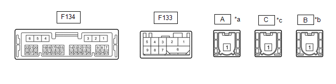
CHECK DCM (TELEMATICS TRANSCEIVER)
|
*a |
Connector Color: Natural (to Telephone Sub Antenna) |
*b |
Connector Color: Blue (to Telephone Main Antenna) |
|
*c |
Connector Color: Gray (to GPS Antenna) |
- |
- |
|
Terminal No. (Symbol) |
Wiring Color |
Terminal Description |
Condition |
Specified Condition |
|---|---|---|---|---|
|
F134-1 (+B) - F134-4 (E) |
W - W-B |
Battery power supply |
Always |
11 to 14 V |
|
F134-2 (SPI+) - F134-4 (E) |
LA-LG - W-B |
Sound signal |
Audio system playing |
A waveform synchronized with sound is output |
|
F134-3 (SPI-) - F134-4 (E) |
LA-L - W-B |
Sound signal |
Audio system playing |
A waveform synchronized with sound is output |
|
F134-4 (E) - Body ground |
W-B - Body ground |
Ground |
Always |
Below 1 V |
|
F134-5 (SPO+) - F134-4 (E) |
LA-LG - W-B |
Sound signal |
Audio system playing, or Emergency call mode |
A waveform synchronized with sound is output |
|
F134-6 (SPO-) - F134-4 (E) |
LA-L - W-B |
Sound signal |
Audio system playing, or Emergency call mode |
A waveform synchronized with sound is output |
|
F134-7 (IG2) - F134-4 (E) |
B - W-B |
IG power supply |
Ignition switch ON |
11 to 14 V |
|
Ignition switch off |
Below 1 V |
|||
|
F134-8 (ACC) - F134-4 (E) |
GR - W-B |
ACC power supply |
Ignition switch ACC |
11 to 14 V |
|
Ignition switch off |
Below 1 V |
|||
|
F134-9 (SLED) - F134-4 (E) |
LG - W-B |
Manual (SOS) switch illumination power supply |
Ignition switch ACC |
11 to 14 V |
|
Ignition switch off |
Below 1 V |
|||
|
F134-11 (IND1) - F134-4 (E) |
B - W-B*3 P - W-B*4 |
Manual (SOS) switch red indicator illumination signal |
For 2 seconds after turning the ignition switch ON |
1 to 8.5 V |
|
Ignition switch off |
Below 1 V |
|||
|
F134-12 (IND2) - F134-4 (E) |
BE - W-B |
Manual (SOS) switch green indicator illumination signal |
For 2 seconds after turning the ignition switch ON |
1 to 8.5 V |
|
Ignition switch off |
Below 1 V |
|||
|
F134-15 (CANP) |
GR |
CAN communication signal |
- |
- |
|
F134-16 (CANN) |
LG |
CAN communication signal |
- |
- |
|
F134-17 (MUTE) - F134-4 (E) |
L - W-B |
Mute signal |
Audio system playing |
3.5 V or higher |
|
Emergency call mode |
Below 1 V |
|||
|
F134-18 (MCO+) - F134-4 (E)*1 |
B - W-B*3 G - W-B*4 |
Sent microphone voice signal |
See "Check Microphone"
|
- |
|
F134-18 (MCO+) - F134-4 (E)*2 |
B - W-B *3 G - W-B*4 |
Sent microphone voice signal |
See "Check Microphone"
|
- |
|
F134-19 (MCO-) - F134-4 (E)*1 |
W - W-B*3 R - W-B*4 |
Sent microphone voice signal |
See "Check Microphone"
|
- |
|
F134-19 (MCO-) - F134-4 (E)*2 |
W - W-B*3 R - W-B*4 |
Sent microphone voice signal |
See "Check Microphone"
|
- |
|
F134-24 (GSW) - F134-4 (E) |
W - W-B |
Collision detection signal |
Ignition switch ON |
Pulse generation (Refer to waveform 1) |
|
F134-26 (SIG-) - F134-4 (E) |
SB - W-B |
Ground |
Always |
Below 1 V |
|
F134-27 (SIG1) - F134-4 (E) |
L - W-B |
Manual (SOS) switch condition signal |
Manual (SOS) switch not pressed |
1.5 to 2.0 V |
|
Manual (SOS) switch pressed |
0.5 to 0.8 V |
|||
|
F134-32 (SGND) - F134-4 (E) |
Shield - W-B |
Shield ground |
Always |
Below 1 V |
|
F134-33 (MCVD) - F134-4 (E) |
B - W-B |
Telephone microphone assembly power supply |
Ignition switch off |
Below 1 V |
|
Ignition switch ACC |
4 to 6 V |
|||
|
F134-34 (MIC+) - F134-4 (E)*1 |
W - W-B |
Receive microphone voice signal |
See "Check Microphone"
|
- |
|
F134-34 (MCI+) - F134-4 (E)*2 |
W - W-B |
Receive microphone voice signal |
See "Check Microphone"
|
- |
|
F134-35 (MCI-) - F134-4 (E)*1 |
R - W-B |
Receive microphone voice signal |
See "Check Microphone"
|
- |
|
F134-35 (MCI-) - F134-4 (E)*2 |
R - W-B |
Receive microphone voice signal |
See "Check Microphone"
|
- |
|
F133-1(USB-) - Body ground |
# |
USB communication line |
- |
- |
|
F133-2(USB+) - Body ground |
# |
USB communication line |
- |
- |
|
F133-3(USBG) - F134-4 (E) |
P - W-B |
DCM (Telematics Transceiver) power supply ground signal |
Always |
Below 1 Ω |
|
F133-4(VOT+) - F134-4 (E) |
G - W-B |
Sent voice signal |
Calling while using the operator service |
A waveform synchronized with the received voice is output |
|
F133-5(USBV) - F134-4 (E) |
Y - W-B |
DCM (Telematics Transceiver) power supply signal |
Ignition switch off |
Below 1 V |
|
Ignition switch ON |
4.5 to 5.25 V |
|||
|
F133-6(USBS) - F134-4 (E) |
Shielded - W-B |
Shield ground |
Always |
Below 1 Ω |
|
F133-7(VOT-) - F134-4 (E) |
W - W-B |
Sent voice signal |
Calling while using the operator service |
A waveform synchronized with the received voice is output |
|
F133-8(VOR-) - F134-4 (E) |
B - W-B |
Receive voice signal |
Receiving a call while using the operator service |
A waveform synchronized with the sent voice is output |
|
F133-9(VOR+) - F134-4 (E) |
R - W-B |
Receive voice signal |
Receiving a call while using the operator service |
A waveform synchronized with the sent voice is output |
- *1: w/o Navigation System
- *2: w/ Navigation System
- *3: for TMMT Made
- *4: for TMC Made
- #: There is no wire color information
(a) Oscilloscope waveform:
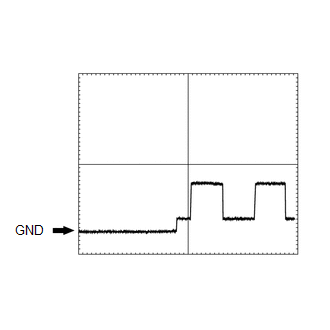
(1) Waveform 1
|
Item |
Condition |
|---|---|
|
Tester connection |
F134-24 (GSW) - F134-4 (E) |
|
Tool setting |
5.0 V/DIV., 20 ms/DIV. |
|
Vehicle condition |
Ignition switch ON |
CHECK RADIO AND DISPLAY RECEIVER ASSEMBLY
w/o Navigation System: Click here
.gif)
w/ Navigation System: Click here
 Problem Symptoms Table
PROBLEM SYMPTOMS TABLE
HINT:
Use the table below to help determine the cause of problem symptoms.
If multiple suspected areas are listed, the potential causes of the symptoms
are lis ...
 Diagnosis System
DIAGNOSIS SYSTEM
DESCRIPTION
(a) The DCM (Telematics Transceiver) control the vehicle safety connect system
functions. Safety connect system data and Diagnostic Trouble Codes (DTCs) can be
read ...
Other materials:
Toyota CH-R Service Manual > Automatic High Beam System: Diagnosis System
DIAGNOSIS SYSTEM
DESCRIPTION
(a) Automatic high beam system data and Diagnostic Trouble Codes (DTCs) can be
read from the Data Link Connector 3 (DLC3) of the vehicle. When the system seems
to be malfunctioning, use the Techstream to check for malfunctions and perform repairs.
CHECK DLC3
(a) ...
Toyota CH-R Service Manual > Rear Door Lock: Inspection
INSPECTION
PROCEDURE
1. INSPECT REAR DOOR LOCK WITH MOTOR ASSEMBLY LH
(a) Check the operation of the door lock motor.
(1) Apply battery voltage and check the operation of the door lock motor.
OK:
Battery Connection
Result
...
Toyota C-HR (AX20) 2023-2026 Owner's Manual
Toyota CH-R Owners Manual
- For safety and security
- Instrument cluster
- Operation of each component
- Driving
- Interior features
- Maintenance and care
- When trouble arises
- Vehicle specifications
- For owners
Toyota CH-R Service Manual
- Introduction
- Maintenance
- Audio / Video
- Cellular Communication
- Navigation / Multi Info Display
- Park Assist / Monitoring
- Brake (front)
- Brake (rear)
- Brake Control / Dynamic Control Systems
- Brake System (other)
- Parking Brake
- Axle And Differential
- Drive Shaft / Propeller Shaft
- K114 Cvt
- 3zr-fae Battery / Charging
- Networking
- Power Distribution
- Power Assist Systems
- Steering Column
- Steering Gear / Linkage
- Alignment / Handling Diagnosis
- Front Suspension
- Rear Suspension
- Tire / Wheel
- Tire Pressure Monitoring
- Door / Hatch
- Exterior Panels / Trim
- Horn
- Lighting (ext)
- Mirror (ext)
- Window / Glass
- Wiper / Washer
- Door Lock
- Heating / Air Conditioning
- Interior Panels / Trim
- Lighting (int)
- Meter / Gauge / Display
- Mirror (int)
- Power Outlets (int)
- Pre-collision
- Seat
- Seat Belt
- Supplemental Restraint Systems
- Theft Deterrent / Keyless Entry

0.0067