Toyota CH-R Service Manual: Speaker Circuit
DESCRIPTION
If there is a short in a speaker circuit, the radio receiver assembly detects it and stops output to the speakers.
Thus sound cannot be heard from the speakers even if there is no malfunction in the radio receiver assembly or speakers.
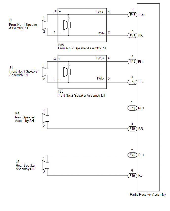
WIRING DIAGRAM
PROCEDURE
|
1. |
CHECK HARNESS AND CONNECTOR (RADIO RECEIVER ASSEMBLY - SPEAKERS) |
(a) Disconnect the F48 and F49 radio receiver assembly connectors.
(b) Disconnect the I1 and J1 front No. 1 speaker assembly connectors.
(c) Disconnect the F85 and F86 front No. 2 speaker assembly connectors.
(d) Disconnect the K4 and L4 rear speaker assembly connectors.
(e) Measure the resistance according to the value(s) in the table below.
Standard Resistance:
|
Tester Connection |
Condition |
Specified Condition |
|---|---|---|
|
F48-1 (FR+) - F85-4 (TWR+) |
Always |
Below 1 Ω |
|
F48-5 (FR-) - F85-2 (TWR-) |
Always |
Below 1 Ω |
|
F85-3 (+) - I1-1 |
Always |
Below 1 Ω |
|
F85-1 (-) - I1-2 |
Always |
Below 1 Ω |
|
F48-2 (FL+) - F86-4 (TWL+) |
Always |
Below 1 Ω |
|
F48-6 (FL-) - F86-2 (TWL-) |
Always |
Below 1 Ω |
|
F86-3 (+) - J1-1 |
Always |
Below 1 Ω |
|
F86-1 (-) - J1-2 |
Always |
Below 1 Ω |
|
F49-1 (RR+) - K4-1 |
Always |
Below 1 Ω |
|
F49-3 (RR-) - K4-2 |
Always |
Below 1 Ω |
|
F49-2 (RL+) - L4-1 |
Always |
Below 1 Ω |
|
F49-6 (RL-) - L4-2 |
Always |
Below 1 Ω |
|
F48-1 (FR+) or F85-4 (TWR+) - Body ground |
Always |
10 kΩ or higher |
|
F48-5 (FR-) or F85-2 (TWR-) - Body ground |
Always |
10 kΩ or higher |
|
F85-3 (+) or I1-1 - Body ground |
Always |
10 kΩ or higher |
|
F85-1 (-) or I1-2 - Body ground |
Always |
10 kΩ or higher |
|
F48-2 (FL+) or F86-4 (TWL+) - Body ground |
Always |
10 kΩ or higher |
|
F48-6 (FL-) or F86-2 (TWL-) - Body ground |
Always |
10 kΩ or higher |
|
F86-3 (+) or J1-1 - Body ground |
Always |
10 kΩ or higher |
|
F86-1 (-) or J1-2 - Body ground |
Always |
10 kΩ or higher |
|
F49-1 (RR+) or K4-1 - Body ground |
Always |
10 kΩ or higher |
|
F49-3 (RR-) or K4-2 - Body ground |
Always |
10 kΩ or higher |
|
F49-2 (RL+) or L4-1 - Body ground |
Always |
10 kΩ or higher |
|
F49-6 (RL-) or L4-2 - Body ground |
Always |
10 kΩ or higher |
| NG | .gif) |
REPAIR OR REPLACE HARNESS OR CONNECTOR |
|
.gif)
|
2. |
INSPECT FRONT NO. 1 SPEAKER ASSEMBLY |
(a) Remove the front No. 1 speaker assembly.
Click here
.gif)
(b) Inspect the front No. 1 speaker assembly.
Click here
| NG | |
REPLACE FRONT NO. 1 SPEAKER ASSEMBLY |
|
|
3. |
INSPECT FRONT NO. 2 SPEAKER ASSEMBLY |
(a) Remove the front No. 2 speaker assembly.
Click here
(b) Inspect the front No. 2 speaker assembly.
Click here
| NG | |
REPLACE FRONT NO. 2 SPEAKER ASSEMBLY |
|
|
4. |
REPLACE FRONT NO. 2 SPEAKER ASSEMBLY |
(a) Check that the malfunction disappears when a known good speaker is installed.
Click here
OK:
Malfunction disappears.
HINT:
- Connect all the connectors to the front No. 2 speaker assemblies that were disconnected.
- When there is a possibility that either the right or left front No. 2 speaker assembly is defective, inspect by interchanging the right one with the left one.
- Perform the above inspection on both LH and RH sides.
| OK | |
END (FRONT NO. 2 SPEAKER ASSEMBLY WAS DEFECTIVE) |
|
|
5. |
INSPECT REAR SPEAKER ASSEMBLY |
(a) Remove the rear speaker assembly.
Click here
(b) Inspect the rear speaker assembly.
Click here
| OK | |
PROCEED TO NEXT SUSPECTED AREA SHOWN IN PROBLEM SYMPTOMS TABLE |
| NG | |
REPLACE REAR SPEAKER ASSEMBLY |
 Illumination Circuit
DESCRIPTION
Power is supplied to the radio receiver assembly and steering pad switch assembly
illumination when the light control switch is in the tail or head position.
WIRING DIAGRAM
CAUTION ...
 Microphone Circuit between Microphone and Radio Receiver
DESCRIPTION
The radio receiver assembly and map light assembly (telephone microphone assembly)
are connected to each other using the microphone connection detection signal lines.
Using this circui ...
Other materials:
Toyota CH-R Service Manual > Audio And Visual System(for Radio And Display Type): Operation Check
OPERATION CHECK
STORAGE CHECK (DCU STORAGE CHECK)
NOTICE:
When replacing the radio and display receiver assembly, always replace it with
a new one. If a radio and display receiver assembly which was installed to another
vehicle is used, the following may occur:
A communication malfunc ...
Toyota CH-R Service Manual > Audio And Visual System(for Radio And Display Type): How To Proceed With Troubleshooting
CAUTION / NOTICE / HINT
HINT:
Use the following procedure to troubleshoot the audio and visual system.
*: Use the Techstream.
PROCEDURE
1.
VEHICLE BROUGHT TO WORKSHOP
NEXT
...
Toyota C-HR (AX20) 2023-2026 Owner's Manual
Toyota CH-R Owners Manual
- For safety and security
- Instrument cluster
- Operation of each component
- Driving
- Interior features
- Maintenance and care
- When trouble arises
- Vehicle specifications
- For owners
Toyota CH-R Service Manual
- Introduction
- Maintenance
- Audio / Video
- Cellular Communication
- Navigation / Multi Info Display
- Park Assist / Monitoring
- Brake (front)
- Brake (rear)
- Brake Control / Dynamic Control Systems
- Brake System (other)
- Parking Brake
- Axle And Differential
- Drive Shaft / Propeller Shaft
- K114 Cvt
- 3zr-fae Battery / Charging
- Networking
- Power Distribution
- Power Assist Systems
- Steering Column
- Steering Gear / Linkage
- Alignment / Handling Diagnosis
- Front Suspension
- Rear Suspension
- Tire / Wheel
- Tire Pressure Monitoring
- Door / Hatch
- Exterior Panels / Trim
- Horn
- Lighting (ext)
- Mirror (ext)
- Window / Glass
- Wiper / Washer
- Door Lock
- Heating / Air Conditioning
- Interior Panels / Trim
- Lighting (int)
- Meter / Gauge / Display
- Mirror (int)
- Power Outlets (int)
- Pre-collision
- Seat
- Seat Belt
- Supplemental Restraint Systems
- Theft Deterrent / Keyless Entry

0.0131