Toyota CH-R Service Manual: Illumination Circuit
DESCRIPTION
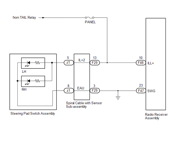
Power is supplied to the radio receiver assembly and steering pad switch assembly illumination when the light control switch is in the tail or head position.
WIRING DIAGRAM
CAUTION / NOTICE / HINT
NOTICE:
- The vehicle is equipped with a Supplemental Restraint System (SRS) which
includes components such as airbags. Before servicing (including removal
or installation of parts), be sure to read the precaution for Supplemental
Restraint System.
Click here
.gif)
- Inspect the fuses for circuits related to this system before performing the following procedure.
PROCEDURE
|
1. |
CHECK ILLUMINATION |
(a) Check if the illumination for the radio receiver assembly, steering pad switch assembly, heater control switch or others (hazard switch, transmission control switch, etc.) comes on when the light control switch is turned to the head or tail position.
|
Result |
Proceed to |
|---|---|
|
Illumination comes on for all components except steering pad switch assembly. |
A |
|
Illumination comes on for all components except radio receiver assembly. |
B |
|
No illumination comes on (radio receiver assembly, hazard switch, heater control switch, etc.). |
C |
| B | .gif) |
GO TO STEP 5 |
| C | |
GO TO LIGHTING SYSTEM |
|
.gif)
|
2. |
CHECK HARNESS AND CONNECTOR (ILLUMINATION SIGNAL) |
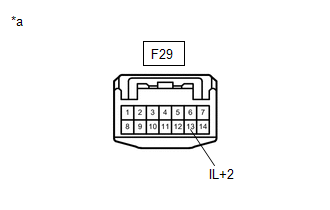
(a) Disconnect the spiral cable with sensor sub-assembly connector.
|
(b) Measure the voltage according to the value(s) in the table below. Standard Voltage:
|
|
| NG | |
REPAIR OR REPLACE HARNESS OR CONNECTOR |
|
|
3. |
INSPECT STEERING PAD SWITCH ASSEMBLY |
(a) Remove the steering pad switch assembly.
Click here
(b) Inspect the steering pad switch assembly.
Click here
(c) Check that the steering pad switch assembly illumination illuminates.
OK:
The steering pad switch assembly illumination illuminates.
| NG | |
REPLACE STEERING PAD SWITCH ASSEMBLY |
|
|
4. |
INSPECT SPIRAL CABLE WITH SENSOR SUB-ASSEMBLY |
(a) Remove the spiral cable with sensor sub-assembly.
Click here
(b) Inspect the spiral cable with sensor sub-assembly.
Click here
NOTICE:
- Press and hold the lock located in the center of the spiral cable with sensor sub-assembly to rotate the spiral cable with sensor sub-assembly.
- The spiral cable with sensor sub-assembly is an important part of the SRS airbag system. Incorrect removal or installation of the spiral cable with sensor sub-assembly may prevent the airbag from deploying.
- As the spiral cable with sensor sub-assembly may break, do not rotate the spiral cable with sensor sub-assembly more than the specified amount.
| OK | |
REPAIR OR REPLACE HARNESS OR CONNECTOR (SPIRAL CABLE WITH SENSOR SUB-ASSEMBLY - RADIO RECEIVER ASSEMBLY - BODY GROUND) |
| NG | |
REPLACE SPIRAL CABLE WITH SENSOR SUB-ASSEMBLY |
|
5. |
CHECK HARNESS AND CONNECTOR (ILLUMINATION SIGNAL) |
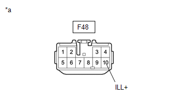
(a) Disconnect the radio receiver assembly connector.
|
(b) Measure the voltage according to the value(s) in the table below. Standard Voltage:
|
|
| OK | |
REPLACE RADIO RECEIVER ASSEMBLY |
| NG | |
REPAIR OR REPLACE HARNESS OR CONNECTOR |
 Steering Pad Switch Circuit
DESCRIPTION
This circuit sends an operation signal from the steering pad switch assembly
to the radio receiver assembly.
If there is an open in the circuit, the audio system cannot be operated usi ...
 Speaker Circuit
DESCRIPTION
If there is a short in a speaker circuit, the radio receiver assembly detects
it and stops output to the speakers.
Thus sound cannot be heard from the speakers even if there is no malf ...
Other materials:
Toyota CH-R Service Manual > Blower Unit(for Denso Made): Installation
INSTALLATION
PROCEDURE
1. INSTALL BLOWER ASSEMBLY
(a) Engage the guides to install the air conditioning radiator assembly.
(b) Install the 2 screws.
(c) Engage the guides.
(d) ...
Toyota CH-R Service Manual > Lighting System: Left Headlight ECU Variation Error (B2456)
DESCRIPTION
This DTC is output when a headlight ECU sub-assembly LH that is incompatible
with the vehicle is installed.
The headlight ECU sub-assembly LH outputs DTC B2456.
DTC No.
Detection Item
DTC Detection Condition
Trouble Area
Note
...
Toyota C-HR (AX20) 2023-2026 Owner's Manual
Toyota CH-R Owners Manual
- For safety and security
- Instrument cluster
- Operation of each component
- Driving
- Interior features
- Maintenance and care
- When trouble arises
- Vehicle specifications
- For owners
Toyota CH-R Service Manual
- Introduction
- Maintenance
- Audio / Video
- Cellular Communication
- Navigation / Multi Info Display
- Park Assist / Monitoring
- Brake (front)
- Brake (rear)
- Brake Control / Dynamic Control Systems
- Brake System (other)
- Parking Brake
- Axle And Differential
- Drive Shaft / Propeller Shaft
- K114 Cvt
- 3zr-fae Battery / Charging
- Networking
- Power Distribution
- Power Assist Systems
- Steering Column
- Steering Gear / Linkage
- Alignment / Handling Diagnosis
- Front Suspension
- Rear Suspension
- Tire / Wheel
- Tire Pressure Monitoring
- Door / Hatch
- Exterior Panels / Trim
- Horn
- Lighting (ext)
- Mirror (ext)
- Window / Glass
- Wiper / Washer
- Door Lock
- Heating / Air Conditioning
- Interior Panels / Trim
- Lighting (int)
- Meter / Gauge / Display
- Mirror (int)
- Power Outlets (int)
- Pre-collision
- Seat
- Seat Belt
- Supplemental Restraint Systems
- Theft Deterrent / Keyless Entry

0.0266