Toyota CH-R Service Manual: Terminals Of Ecu
TERMINALS OF ECU
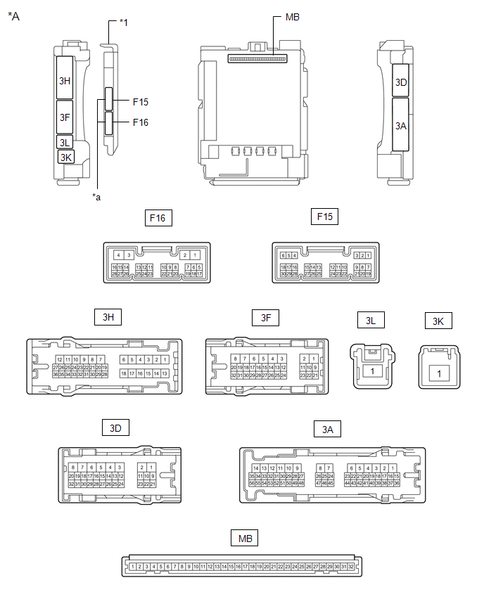
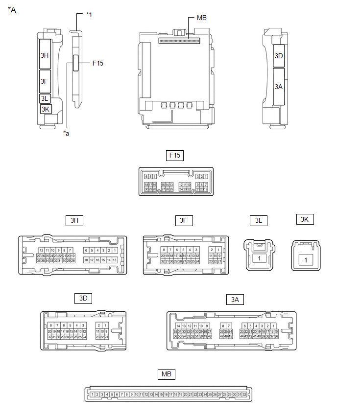
CHECK INSTRUMENT PANEL JUNCTION BLOCK ASSEMBLY AND MAIN BODY ECU (MULTIPLEX NETWORK BODY ECU)
|
*A |
Main Body ECU (Multiplex Network Body ECU) with 2 Connectors |
- |
- |
|
*1 |
Main Body ECU (Multiplex Network Body ECU) |
- |
- |
|
*a |
2 Connectors |
- |
- |
|
*A |
Main Body ECU (Multiplex Network Body ECU) with 1 Connector |
- |
- |
|
*1 |
Main Body ECU (Multiplex Network Body ECU) |
- |
- |
|
*a |
1 Connector |
- |
- |
(a) Remove the main body ECU (multiplex network body ECU) from the instrument panel junction block assembly.
Click here .gif)
(b) Reconnect the instrument panel junction block assembly connectors.
(c) Measure the resistance and voltage according to the value(s) in the table below.
HINT:
Measure the values on the wire harness side with the connector disconnected.
|
Terminal No. (Symbol) |
Wiring Color |
Terminal Description |
Condition |
Specified Condition |
|---|---|---|---|---|
|
MB-31 (BECU) - Body ground |
- |
Battery power supply |
Always |
11 to 14 V |
|
MB-32 (IG) - Body ground |
- |
Ignition power supply (IG signal) |
Ignition switch off |
Below 1 V |
|
Ignition switch ON |
11 to 14 V |
|||
|
MB-30 (ACC) - Body ground |
- |
Ignition power supply (ACC signal) |
Ignition switch off |
Below 1 V |
|
Ignition switch ACC |
11 to 14 V |
|||
|
MB-11 (GND1) - Body ground |
- |
Ground |
Always |
Below 1 Ω |
|
F15-6 (FLCY) - Body ground |
R - Body ground |
Front door courtesy light switch assembly LH input |
Front door LH closed |
10 kΩ or higher |
|
Front door LH open |
Below 1 Ω |
|||
|
F15-27 (FRCY) - Body ground |
BR - Body ground |
Front door courtesy light switch assembly RH input |
Front door RH closed |
10 kΩ or higher |
|
Front door RH open |
Below 1 Ω |
|||
|
MB-13 (LCTY) - Body ground |
- |
Rear door courtesy light switch assembly LH input |
Rear door LH closed |
10 kΩ or higher |
|
Rear door LH open |
Below 1 Ω |
|||
|
MB-2 (RCTY) - Body ground |
- |
Rear door courtesy light switch assembly RH input |
Rear door RH closed |
10 kΩ or higher |
|
Rear door RH open |
Below 1 Ω |
|||
|
MB-4 (BCTY) - Body ground |
- |
Back door courtesy light switch input |
Back door closed |
10 kΩ or higher |
|
Back door open |
Below 1 Ω |
|||
|
F15-11 (HCTY) - Body ground |
GR - Body ground |
Hood courtesy switch input |
Hood open |
10 kΩ or higher |
|
Hood closed |
Below 1 Ω |
|||
|
MB-3 (KSW) - Body ground*1 |
- |
Unlock warning switch signal |
No key in ignition key cylinder |
10 kΩ or higher |
|
Key in ignition key cylinder |
Below 1 Ω |
- *1: w/o Smart Key System
(d) Install the main body ECU (multiplex network body ECU) to instrument panel junction block assembly.
Click here
(e) Measure the voltage and check for pulses according to the value(s) in the table below.
|
Terminal No. (Symbol) |
Wiring Color |
Terminal Description |
Condition |
Specified Condition |
|---|---|---|---|---|
|
3D-13 (LSFL) - Body ground |
B - Body ground |
Front door LH unlock detection switch input |
Front door LH unlocked |
Below 1 V |
|
Front door LH locked |
Pulse generation |
|||
|
3D-12 (LSFR) - Body ground |
GR - Body ground |
Front door RH unlock detection switch input |
Front door RH unlocked |
Below 1 V |
|
Front door RH locked |
Pulse generation |
|||
|
F15-29 (L2) - Body ground |
G - Body ground |
Driver door key-linked lock input |
Driver door key cylinder turned to lock position |
Below 1 V |
|
Driver door key cylinder off |
Pulse generation |
|||
|
F15-2 (UL3) - Body ground |
L - Body ground |
Driver door key-linked unlock input |
Driver door key cylinder turned to unlock position |
Below 1 V |
|
Driver door key cylinder off |
Pulse generation |
|||
|
3D-14 (LSR) - Body ground |
LG - Body ground |
Rear door LH and Rear door RH unlock detection switch input |
Rear door LH or Rear door RH unlocked |
Below 1 V |
|
Rear door LH and Rear door RH locked |
Pulse generation |
|||
|
3A-20 (SH) - Body ground |
LG - Body ground |
Security horn assembly drive |
Security horn assembly sounding (Theft deterrent system in alarm sounding state) |
Pulse generation (Below 1 V ← → 11 to 14 V) |
|
3F-27 (HORN) - Body ground |
SB - Body ground |
Vehicle horns drive |
Vehicle horns sounding (Theft deterrent system in alarm sounding state) |
Pulse generation (Below 1 V ← → 11 to 14 V) |
 Problem Symptoms Table
PROBLEM SYMPTOMS TABLE
NOTICE:
Before replacing the main body ECU (multiplex network body ECU), refer
to REGISTRATION*1.
Click here
*1: w/ Smart Key System
When replacing ...
 Data List / Active Test
DATA LIST / ACTIVE TEST
DATA LIST
HINT:
Using the Techstream to read the Data List allows the values or states of switches,
sensors, actuators and other items to be read without removing any part ...
Other materials:
Toyota CH-R Service Manual > Refrigerant Line: Removal
REMOVAL
PROCEDURE
1. RECOVER REFRIGERANT FROM REFRIGERATION SYSTEM
for HFC-134a(R134a):
Click here
for HFO-1234yf(R1234yf):
Click here
2. REMOVE PIPING CLAMP (for DENSO Made)
(a) for Suction Hose Sub-assembly:
(1) While pressing the end of the sucti ...
Toyota CH-R Service Manual > Lumbar Switch: Installation
INSTALLATION
CAUTION / NOTICE / HINT
CAUTION:
Be sure to read Precaution thoroughly before servicing.
Click here
Wear protective gloves. Sharp areas on the parts may injure your hands.
HINT:
Front lumbar power seat switch is available only on the driver side ...
Toyota C-HR (AX20) 2023-2026 Owner's Manual
Toyota CH-R Owners Manual
- For safety and security
- Instrument cluster
- Operation of each component
- Driving
- Interior features
- Maintenance and care
- When trouble arises
- Vehicle specifications
- For owners
Toyota CH-R Service Manual
- Introduction
- Maintenance
- Audio / Video
- Cellular Communication
- Navigation / Multi Info Display
- Park Assist / Monitoring
- Brake (front)
- Brake (rear)
- Brake Control / Dynamic Control Systems
- Brake System (other)
- Parking Brake
- Axle And Differential
- Drive Shaft / Propeller Shaft
- K114 Cvt
- 3zr-fae Battery / Charging
- Networking
- Power Distribution
- Power Assist Systems
- Steering Column
- Steering Gear / Linkage
- Alignment / Handling Diagnosis
- Front Suspension
- Rear Suspension
- Tire / Wheel
- Tire Pressure Monitoring
- Door / Hatch
- Exterior Panels / Trim
- Horn
- Lighting (ext)
- Mirror (ext)
- Window / Glass
- Wiper / Washer
- Door Lock
- Heating / Air Conditioning
- Interior Panels / Trim
- Lighting (int)
- Meter / Gauge / Display
- Mirror (int)
- Power Outlets (int)
- Pre-collision
- Seat
- Seat Belt
- Supplemental Restraint Systems
- Theft Deterrent / Keyless Entry

0.0088