Toyota CH-R Service Manual: Terminals Of Ecu
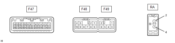
TERMINALS OF ECU
|
Terminal No. (Symbol) |
Wiring Color |
Terminal Description |
Condition |
Specified Condition |
|---|---|---|---|---|
|
F47-4 (MACC) - F48-7 (GND1) |
B - LA |
Microphone power supply |
Ignition switch off |
Below 1 V |
|
Ignition switch ACC |
4 to 6 V |
|||
|
F47-5 (MIN+) - F48-7 (GND1) |
W - LA |
Microphone voice signal |
"Bluetooth" hands-free voice signal received |
A waveform synchronized with sound signals is output |
|
F47-6 (SNS2) - F48-7 (GND1) |
V - LA |
Microphone connection detection signal |
Always |
Below 1 V |
|
F47-17 (SPD) - F48-7 (GND1) |
V - LA |
Vehicle speed signal |
Ignition switch ON Wheel being rotated |
Pulse generation |
|
F47-18 (SGND) - Body ground |
Shield - Body ground |
Shield ground |
Always |
Below 1 V |
|
F47-19 (MIN-) - F48-7 (GND1) |
R - LA |
Microphone voice signal |
"Bluetooth" hands-free voice signal received |
A waveform synchronized with sound signals is output |
|
F47-21 (SW1) - F47-23 (SWG) |
GR - W-B |
Steering pad switch signal |
No switch pushed |
2.97 to 3.56 V |
|
Seek+ switch pushed |
0.27 to 0.35 V |
|||
|
Seek- switch pushed |
0.86 to 1.03 V |
|||
|
Volume+ switch pushed |
1.51 to 1.79 V |
|||
|
Volume- switch pushed |
2.22 to 2.66 V |
|||
|
F47-22 (SW2) - F47-23 (SWG) |
G - W-B |
Steering pad switch signal |
No switch pushed |
2.97 to 3.56 V |
|
MODE switch pushed |
0.27 to 0.35 V |
|||
|
On hook switch pushed |
0.86 to 1.03 V |
|||
|
Off hook switch pushed |
1.51 to 1.79 V |
|||
|
F47-23 (SWG) - Body ground |
W-B - Body ground |
Steering pad switch signal |
Always |
Below 1 V |
|
F48-1 (FR+) - F48-7 (GND1) |
P - LA |
Sound signal (Front Right) |
Audio system playing |
A waveform synchronized with sound signals is output |
|
F48-2 (FL+) - F48-7 (GND1) |
W - LA |
Sound signal (Front Left) |
Audio system playing |
A waveform synchronized with sound signals is output |
|
F48-3 (ACC1) - F48-7 (GND1) |
GR - LA |
Power source (ACC) |
Ignition switch off |
Below 1 V |
|
Ignition switch ACC |
11 to 14 V |
|||
|
F48-4 (+B1) - F48-7 (GND1) |
LA-SB - LA |
Power source (+B) |
Always |
11 to 14 V |
|
F48-5 (FR-) - F48-7 (GND1) |
BR - LA |
Sound signal (Front Right) |
Audio system playing |
A waveform synchronized with sound signals is output |
|
F48-6 (FL-) - F48-7 (GND1) |
B - LA |
Sound signal (Front Left) |
Audio system playing |
A waveform synchronized with sound signals is output |
|
F48-7 (GND1) - Body ground |
LA - Body ground |
Ground |
Always |
Below 1 V |
|
F48-10 (ILL+) - Body ground |
G - Body ground |
Illumination signal |
Light control switch off |
Below 1 V |
|
Light control switch in tail or head position |
11 to 14 V |
|||
|
F49-1 (RR+) - F48-7 (GND1) |
R - LA |
Sound signal (Rear Right) |
Audio system playing |
A waveform synchronized with sound signals is output |
|
F49-2 (RL+) - F48-7 (GND1) |
B - LA |
Sound signal (Rear Left) |
Audio system playing |
A waveform synchronized with sound signals is output |
|
F49-3 (RR-) - F48-7 (GND1) |
W - LA |
Sound signal (Rear Right) |
Audio system playing |
A waveform synchronized with sound signals is output |
|
F49-6 (RL-) - F48-7 (GND1) |
Y - LA |
Sound signal (Rear Left) |
Audio system playing |
A waveform synchronized with sound signals is output |
|
RA-5 (ANT+) - F48-7 (GND1) |
- - LA |
Power source of antenna |
Ignition switch ACC Radio switch on and AM or FM selected |
11 to 14 V |
 Problem Symptoms Table
PROBLEM SYMPTOMS TABLE
HINT:
Use the table below to help determine the cause of problem symptoms.
If multiple suspected areas are listed, the potential causes of the symptoms
are lis ...
 Noise Occurs
PROCEDURE
1.
NOISE CONDITION
(a) Check from which direction the noise comes (front left or right, rear left
or right).
OK:
The location of the noise source can b ...
Other materials:
Toyota CH-R Service Manual > Generator: Components
COMPONENTS
ILLUSTRATION
*1
GENERATOR ASSEMBLY
*2
TERMINAL CAP
*3
WIRE HARNESS CLAMP BRACKET
-
-
Tightening torque for "Major areas involving basic vehicle performance
...
Toyota CH-R Service Manual > Air Conditioning System(for Automatic Air Conditioning System With Top-mounted
Air Conditioner Pressure Sensor): System Description
SYSTEM DESCRIPTION
GENERAL
The air conditioning system has the following controls.
Control
Outline
Neural Network Control
This control is capable of performing complex control by artificially
simulating the information processing method of the ...
Toyota C-HR (AX20) 2023-2026 Owner's Manual
Toyota CH-R Owners Manual
- For safety and security
- Instrument cluster
- Operation of each component
- Driving
- Interior features
- Maintenance and care
- When trouble arises
- Vehicle specifications
- For owners
Toyota CH-R Service Manual
- Introduction
- Maintenance
- Audio / Video
- Cellular Communication
- Navigation / Multi Info Display
- Park Assist / Monitoring
- Brake (front)
- Brake (rear)
- Brake Control / Dynamic Control Systems
- Brake System (other)
- Parking Brake
- Axle And Differential
- Drive Shaft / Propeller Shaft
- K114 Cvt
- 3zr-fae Battery / Charging
- Networking
- Power Distribution
- Power Assist Systems
- Steering Column
- Steering Gear / Linkage
- Alignment / Handling Diagnosis
- Front Suspension
- Rear Suspension
- Tire / Wheel
- Tire Pressure Monitoring
- Door / Hatch
- Exterior Panels / Trim
- Horn
- Lighting (ext)
- Mirror (ext)
- Window / Glass
- Wiper / Washer
- Door Lock
- Heating / Air Conditioning
- Interior Panels / Trim
- Lighting (int)
- Meter / Gauge / Display
- Mirror (int)
- Power Outlets (int)
- Pre-collision
- Seat
- Seat Belt
- Supplemental Restraint Systems
- Theft Deterrent / Keyless Entry

0.008