Toyota CH-R Service Manual: Ignition Hold Monitor Malfunction (B2271)
DESCRIPTION
This DTC is stored when a malfunction in the IG circuit or IG hold circuit of the certification ECU (smart key ECU assembly) is detected.
|
DTC No. |
Detection Item |
DTC Detection Condition |
Trouble Area |
Note |
|---|---|---|---|---|
|
B2271 |
Ignition Hold Monitor Malfunction |
When either of the following conditions is met (1-trip detection logic*1):
|
|
|
- *1: Only detected while a malfunction is present and the engine switch is on (IG).
- *2: The IG circuit and IG hold circuit activate the IG relay.
- *3: After the IG circuit turns on, even if the certification ECU (smart key ECU assembly) malfunctions, the IG hold circuit will maintain the power source mode in on (IG).
|
Vehicle Condition |
|||
|---|---|---|---|
|
Pattern 1 |
Pattern 2 |
||
|
Diagnosis Condition |
Turn the engine switch on (IG). |
○ |
○ |
|
Malfunction Status |
The IG circuit in the certification ECU (smart key ECU assembly) is malfunctioning. |
○ |
- |
|
The IG hold circuit in the certification ECU (smart key ECU assembly) is malfunctioning. |
- |
○ |
|
|
Detection Time |
- |
- |
|
|
Number of Trips |
1 trip |
1 trip |
|
HINT:
DTC will be output when conditions for either of the patterns in the table above are met.
Vehicle Condition and Fail-safe Function when Malfunction Detected|
Vehicle Condition when Malfunction Detected |
Fail-safe Function when Malfunction Detected |
|---|---|
|
The engine switch cannot be turned on (IG) (the engine cannot be started). |
The power source mode cannot be changed to on (IG). |
|
DTC No. |
Data List and Active Test |
|---|---|
|
B2271 |
Power Source Control
Starting Control
|
WIRING DIAGRAM
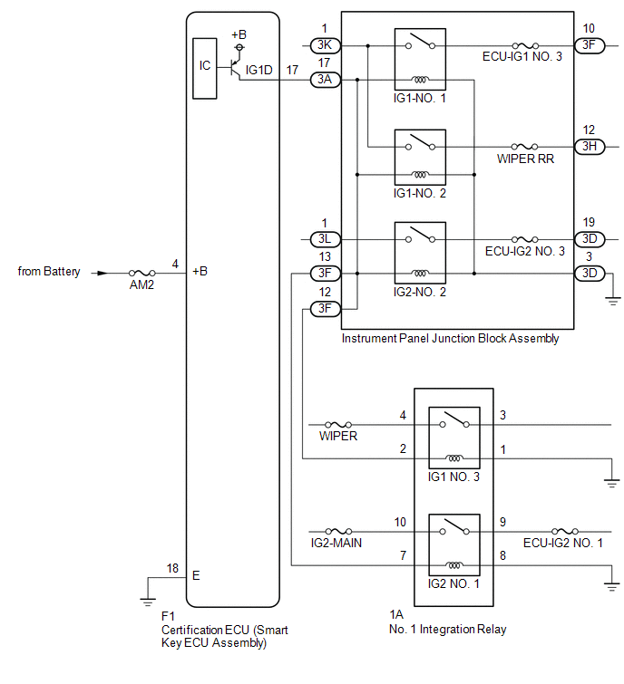
CAUTION / NOTICE / HINT
NOTICE:
- When using the Techstream with the engine switch off, connect the Techstream to the DLC3 and turn a courtesy light switch on and off at intervals of 1.5 seconds or less until communication between the Techstream and the vehicle begins. Then select the vehicle type under manual mode and enter the following menus: Body Electrical / Smart Key. While using the Techstream, periodically turn a courtesy light switch on and off at intervals of 1.5 seconds or less to maintain communication between the Techstream and the vehicle.
- The smart key system (for Start Function) uses the LIN communication
system and CAN communication system. Inspect the communication function
by following How to Proceed with Troubleshooting. Troubleshoot the smart
key system (for Start Function) after confirming that the communication
systems are functioning properly.
Click here
.gif)
- Inspect the fuses of circuits related to this system before performing the following procedure.
- Before replacing the certification ECU (smart key ECU assembly), refer
to smart key system (for Start Function) Precaution.
Click here
- After repair, confirm that no DTCs are output by performing "DTC Output Confirmation Operation".
HINT:
When the cable is disconnected and reconnected to the negative (-) battery terminal, the power source mode returns to the state it was in before the cable was disconnected.
PROCEDURE
|
1. |
CHECK HARNESS AND CONNECTOR (POWER SOURCE) |
|
(a) Disconnect the certification ECU (smart key ECU assembly) connector. |
|
(b) Measure the voltage according to the value(s) in the table below.
Standard Voltage:
|
Tester Connection |
Condition |
Specified Condition |
|---|---|---|
|
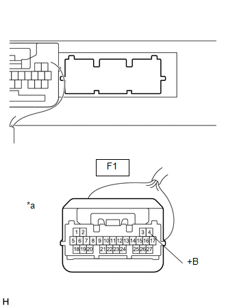
F1-4 (+B) - Body ground |
Always |
11 to 14 V |
| NG | .gif) |
REPAIR OR REPLACE HARNESS OR CONNECTOR IN CIRCUIT CONNECTED TO POWER SOURCE |
|
.gif)
|
2. |
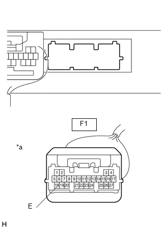
CHECK HARNESS AND CONNECTOR (GROUND) |
(a) Disconnect the certification ECU (smart key ECU assembly) connector.
|
(b) Measure the resistance according to the value(s) in the table below. Standard Resistance:
|
|
| NG | |
REPAIR OR REPLACE HARNESS OR CONNECTOR |
|
|
3. |
CHECK CERTIFICATION ECU (SMART KEY ECU ASSEMBLY) |
|
(a) Reconnect the F1 certification ECU (smart key ECU assembly) connector. |
|
(b) Measure the voltage according to the value(s) in the table below.
Standard Voltage:
|
Tester Connection |
Switch Condition |
Specified Condition |
|---|---|---|
|
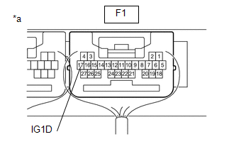
F1-17 (IG1D) - Body ground |
Engine switch on (ACC) → Engine switch on (IG) |
1 V or less → 9 V or higher |
| OK | |
END (TEMPORARY CONNECTION FAILURE IS SUSPECTED)
|
| NG | |
REPLACE CERTIFICATION ECU (SMART KEY ECU ASSEMBLY) |
 Lost Communication with ECM / PCM (U0100,U0140,U0142,U0155,U1117)
DESCRIPTION
These DTCs are stored when there is a CAN communication malfunction between the
certification ECU (smart key ECU assembly), ECM, main body ECU (multiplex network
body ECU) or combinat ...
 ACC Monitor Malfunction (B2274)
DESCRIPTION
This DTC is stored when a malfunction in the ACC output circuit is detected.
The ACC output circuit is the circuit between terminal ACCD of the certification
ECU (smart key ECU assemb ...
Other materials:
Toyota CH-R Service Manual > Rear Door Lock: Inspection
INSPECTION
PROCEDURE
1. INSPECT REAR DOOR LOCK WITH MOTOR ASSEMBLY LH
(a) Check the operation of the door lock motor.
(1) Apply battery voltage and check the operation of the door lock motor.
OK:
Battery Connection
Result
...
Toyota CH-R Service Manual > Airbag System: SRS Warning Light does not Come ON
DESCRIPTION
The SRS warning light is located in the combination meter assembly.
When the SRS is normal, the SRS warning light comes on for approximately 6 seconds
after the ignition switch is turned from off to ON, and then goes off automatically.
If there is a malfunction in the SRS, the SRS w ...
Toyota C-HR (AX20) 2023-2026 Owner's Manual
Toyota CH-R Owners Manual
- For safety and security
- Instrument cluster
- Operation of each component
- Driving
- Interior features
- Maintenance and care
- When trouble arises
- Vehicle specifications
- For owners
Toyota CH-R Service Manual
- Introduction
- Maintenance
- Audio / Video
- Cellular Communication
- Navigation / Multi Info Display
- Park Assist / Monitoring
- Brake (front)
- Brake (rear)
- Brake Control / Dynamic Control Systems
- Brake System (other)
- Parking Brake
- Axle And Differential
- Drive Shaft / Propeller Shaft
- K114 Cvt
- 3zr-fae Battery / Charging
- Networking
- Power Distribution
- Power Assist Systems
- Steering Column
- Steering Gear / Linkage
- Alignment / Handling Diagnosis
- Front Suspension
- Rear Suspension
- Tire / Wheel
- Tire Pressure Monitoring
- Door / Hatch
- Exterior Panels / Trim
- Horn
- Lighting (ext)
- Mirror (ext)
- Window / Glass
- Wiper / Washer
- Door Lock
- Heating / Air Conditioning
- Interior Panels / Trim
- Lighting (int)
- Meter / Gauge / Display
- Mirror (int)
- Power Outlets (int)
- Pre-collision
- Seat
- Seat Belt
- Supplemental Restraint Systems
- Theft Deterrent / Keyless Entry

0.0166