Toyota CH-R Service Manual: System Diagram
SYSTEM DIAGRAM
|
Component |
Outline |
|---|---|
|
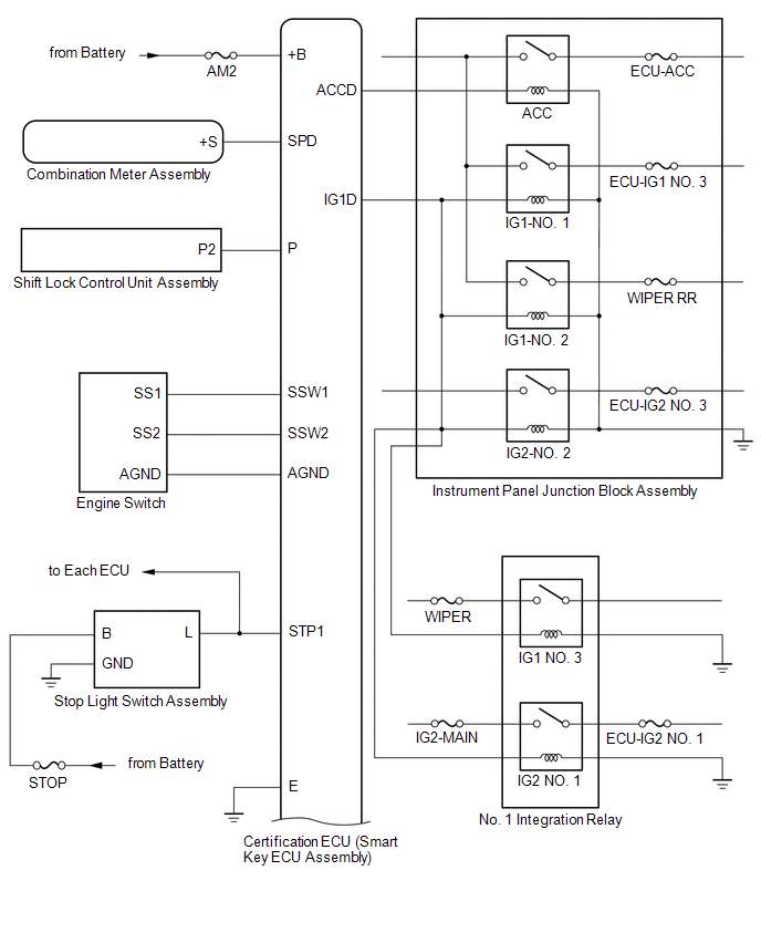
Engine switch
|
|
|
Certification ECU (smart key ECU assembly) |
|
|
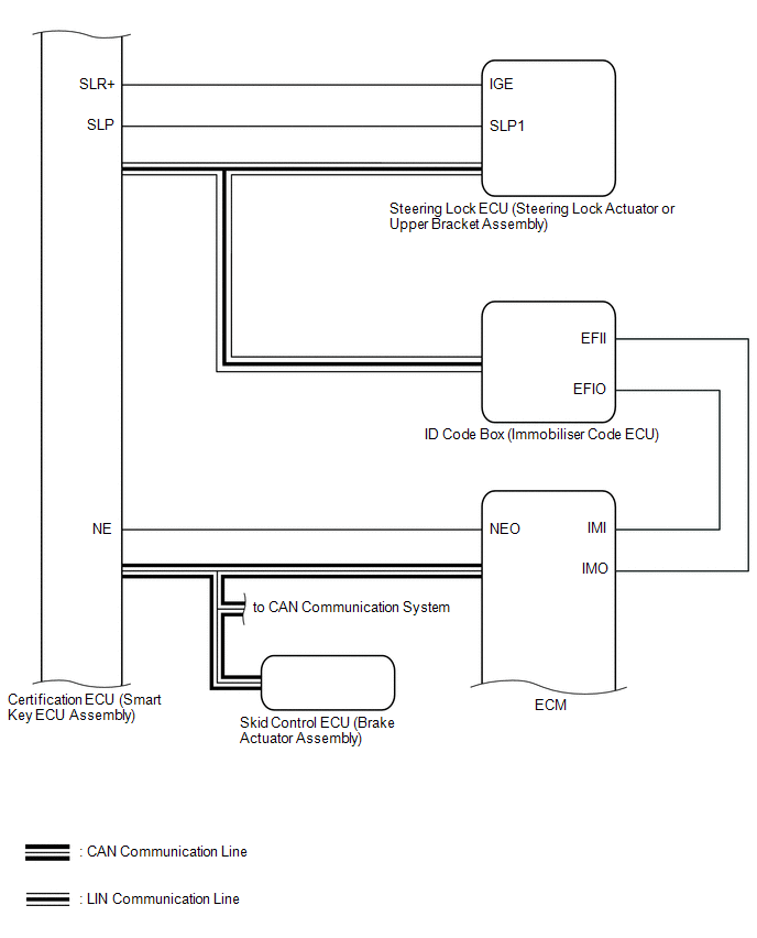
ID code box (immobiliser code ECU) |
|
|
ECM |
Outputs a signal indicating that the engine has started to the certification ECU (smart key ECU assembly) when starting the engine. |
|
Steering lock ECU (steering lock actuator or upper bracket assembly) |
|
|
Combination meter assembly |
|
|
IG, ACC relay |
Turns on/off according to the certification ECU (smart key ECU assembly) and provides power to each system. |
|
Stop light switch assembly |
Detects when the brake pedal is depressed (switch is on) and outputs a signal to the certification ECU (smart key ECU assembly). |
|
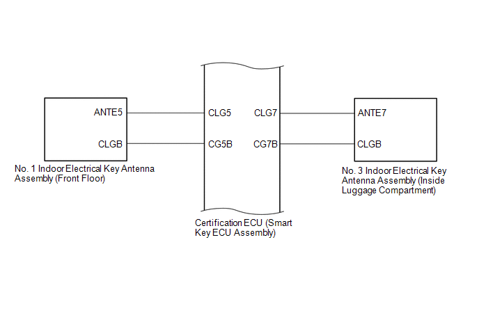
Sends the request code from the certification ECU (smart key ECU assembly) and forms the vehicle interior detection area. |
|
Electrical key transmitter sub-assembly |
Sends an ID code upon receiving a request signal. |
|
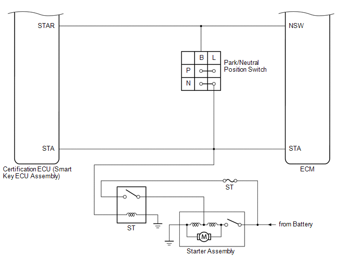
Park/neutral position switch |
Outputs the shift position to the certification ECU (smart key ECU assembly) |
|
Shift lock control unit assembly |
Outputs a shift lock control ECU signal to the certification ECU (smart key ECU assembly). |
|
Electrical key and TPMS receiver assembly |
Receives the smart key system code/wireless code sent from the electrical key transmitter subassembly and sends it to the certification ECU (smart key ECU assembly). |
 Precaution
PRECAUTION
CAUTION REGARDING INTERFERENCE WITH ELECTRONIC DEVICES
CAUTION:
People with implantable cardiac pacemakers, cardiac resynchronization
therapy-pacemakers or implantable cardio ...
 How To Proceed With Troubleshooting
CAUTION / NOTICE / HINT
HINT:
Use these procedures to troubleshoot the smart key system (for Start
Function).
*: Use the Techstream.
PROCEDURE
1.
VEHIC ...
Other materials:
Toyota CH-R Owners Manual > Using the driving support systems: LDA (Lane Departure Alert with steering control)
Summary of functions
When driving on highways and freeways with white (yellow) lines, this function
alerts the driver when the vehicle might depart from its lane and provides assistance
by operating the steering wheel to keep the vehicle in its lane.
The LDA system recognizes visible white (ye ...
Toyota CH-R Service Manual > Navigation System: Cellular Phone Registration Failure
CAUTION / NOTICE / HINT
NOTICE:
Depending on the parts that are replaced during vehicle inspection or
maintenance, performing initialization, registration or calibration may
be needed. Refer to Precaution for Navigation System.
Click here
When replacing the radio ...
Toyota C-HR (AX20) 2023-2026 Owner's Manual
Toyota CH-R Owners Manual
- For safety and security
- Instrument cluster
- Operation of each component
- Driving
- Interior features
- Maintenance and care
- When trouble arises
- Vehicle specifications
- For owners
Toyota CH-R Service Manual
- Introduction
- Maintenance
- Audio / Video
- Cellular Communication
- Navigation / Multi Info Display
- Park Assist / Monitoring
- Brake (front)
- Brake (rear)
- Brake Control / Dynamic Control Systems
- Brake System (other)
- Parking Brake
- Axle And Differential
- Drive Shaft / Propeller Shaft
- K114 Cvt
- 3zr-fae Battery / Charging
- Networking
- Power Distribution
- Power Assist Systems
- Steering Column
- Steering Gear / Linkage
- Alignment / Handling Diagnosis
- Front Suspension
- Rear Suspension
- Tire / Wheel
- Tire Pressure Monitoring
- Door / Hatch
- Exterior Panels / Trim
- Horn
- Lighting (ext)
- Mirror (ext)
- Window / Glass
- Wiper / Washer
- Door Lock
- Heating / Air Conditioning
- Interior Panels / Trim
- Lighting (int)
- Meter / Gauge / Display
- Mirror (int)
- Power Outlets (int)
- Pre-collision
- Seat
- Seat Belt
- Supplemental Restraint Systems
- Theft Deterrent / Keyless Entry

0.0102