Toyota CH-R Service Manual: Terminals Of Ecu
TERMINALS OF ECU
CHECK CERTIFICATION ECU (SMART KEY ECU ASSEMBLY)
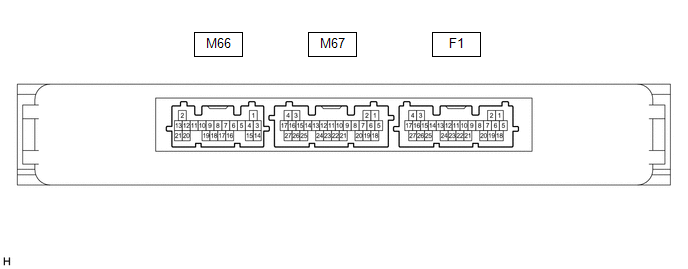
(a) Disconnect the F1 certification ECU (smart key ECU assembly) connector.
(b) Measure the voltage and resistance according to the value(s) in the table below.
HINT:
Measure the values on the wire harness side with the connector disconnected.
|
Terminal No. (Symbol) |
Input/Output |
Wiring Color |
Terminal Description |
Condition |
Specified Condition |
Related Data List Item |
|---|---|---|---|---|---|---|
|
F1-18 (E) - Body ground |
- |
W-B - Body ground |
Ground |
Always |
Below 1 Ω |
- |
|
F1-4 (+B) - F1-18 (E) |
Input |
L - W-B |
Power supply |
Always |
11 to 14 V |
- |
|
F1-15 (CUTB) - F1-18 (E) |
Input |
SB - W-B |
Dark current cut pin* |
Always |
11 to 14 V |
- |
- *: In order to prevent the vehicle battery from being depleted when the vehicle is shipped long distances, a fuse that cuts unnecessary electrical load while the vehicle is being shipped is installed in the circuit. If the fuse is removed, the circuit becomes open. If the fuse that is between the vehicle battery and terminal CUTB is removed and the circuit is open, the certification ECU (smart key ECU assembly) changes to a certain control mode (example: the transmission of radio waves every 0.25 seconds, which form the detection area, stops).
(c) Reconnect the F1 certification ECU (smart key ECU assembly) connector.
(d) Measure the voltage and check for pulses according to the value(s) in the table below.
|
Tester Connection |
Input/Output |
Wiring Color |
Terminal Description |
Condition |
Specified Condition |
Related Data List Item |
|---|---|---|---|---|---|---|
|
F1-17 (IG1D) - F1-18 (E) |
Output |
GR - W-B |
IG power supply |
Engine switch off → on (IG) |
Below 1 V → 10 V or higher |
- |
|
M67-17 (CLG1) - F1-18 (E) |
Output |
G - W-B |
Output to driver door electrical key antenna (request signal (challenge) is sent to door electrical key antenna from certification ECU (smart key ECU assembly) to form detection area) |
Procedure:
|
Pulse generation (See waveform 1) |
Overhead + Driver Side (key diagnostic mode) |
|
Procedure:
|
Pulse generation (See waveform 2) |
|||||
|
M67-17 (CLG1) - F1-18 (E) |
Input |
G - W-B |
Input to driver door lock sensor (front door outside handle assembly LH lock sensor on signal is sent to the certification ECU (smart key ECU assembly)) |
Procedure:
|
Pulse generation (See waveform 3) |
D-Door Trigger Switch |
|
M67-17 (CLG1) - F1-18 (E) |
Input |
G - W-B |
Input to driver door unlock sensor (when system is in unlock standby mode and unlock sensor is touched, door electrical key antenna sends unlock sensor input signal (sensing) to certification ECU (smart key ECU assembly)) |
Procedure:
|
Pulse generation (See waveform 4) |
D-Door Touch Sensor |
|
M67-16 (CG1B) - F1-18 (E) |
Output |
R - W-B |
Output to driver door electrical key antenna (terminal on opposite side of component from CLG1 output terminal) |
Procedure:
|
Pulse generation (See waveform 5) |
Overhead + Driver Side (key diagnostic mode) |
|
Procedure:
|
Pulse generation (See waveform 6) |
|||||
|
M67-15 (CLG2) - F1-18 (E) |
Output |
G - W-B*2 P - W-B*3 |
Output to front passenger door electrical key antenna (request signal (challenge) is sent to door electrical key antenna from certification ECU (smart key ECU assembly) to form detection area) |
Procedure:
|
Pulse generation (See waveform 1) |
Overhead + Passenger Side (key diagnostic mode) |
|
Procedure:
|
Pulse generation (See waveform 2) |
|||||
|
M67-15 (CLG2) - F1-18 (E) |
Input |
G - W-B*2 P - W-B*3 |
Input to front passenger door lock sensor (front door outside handle assembly RH lock sensor on signal is sent to the certification ECU (smart key ECU assembly)) |
Procedure:
|
Pulse generation (See waveform 3) |
P-Door Trigger Switch |
|
M67-15 (CLG2) - F1-18 (E) |
Input |
G - W-B*2 P - W-B*3 |
Input to front passenger door unlock sensor (when system is in unlock standby mode and unlock sensor is touched, door electrical key antenna sends unlock sensor input signal (sensing) to certification ECU (smart key ECU assembly)) |
Procedure:
|
Pulse generation (See waveform 4) |
P-Door Touch Sensor |
|
M67-14 (CG2B) - F1-18 (E) |
Output |
R - W-B |
Output to front passenger door electrical key antenna (terminal on opposite side of component from CLG2 output terminal) |
Procedure:
|
Pulse generation (See waveform 5) |
Overhead + Passenger Side (key diagnostic mode) |
|
Procedure:
|
Pulse generation (See waveform 6) |
|||||
|
F1-8 (CLG5) - F1-18 (E) |
Output |
SB - W-B |
Output to No. 1 indoor electrical key antenna assembly (front floor) |
Procedure:
|
Pulse generation (See waveform 7) |
Overhead + Front Room (key diagnostic mode) |
|
F1-9 (CG5B) - F1-18 (E) |
Output |
R - W-B |
Output to No. 1 indoor electrical key antenna assembly (front floor) (terminal on opposite side of component from CLG5 output terminal) |
Procedure:
|
Pulse generation (See waveform 7) |
Overhead + Front Room (key diagnostic mode) |
|
M67-11 (CLG7) - F1-18 (E) |
Output |
B - W-B |
Output to No. 3 indoor electrical key antenna assembly (inside luggage compartment) |
Procedure:
|
Pulse generation (See waveform 7) |
Overhead + Back Door (inside) (key diagnostic mode) |
|
M67-10 (CG7B) - F1-18 (E) |
Output |
W - W-B |
Output to No. 3 indoor electrical key antenna assembly (inside luggage compartment) (terminal on opposite side of component from CLG7 output terminal) |
Procedure:
|
Pulse generation (See waveform 7) |
Overhead + Back Door (inside) (key diagnostic mode) |
|
M67-13 (CLG8) - F1-18 (E) |
Output |
Y - W-B |
Output to electrical key antenna (outside luggage compartment) |
Procedure:
|
Pulse generation (See waveform 8) |
Overhead + Back Door (key diagnostic mode) |
|
M67-12 (CG8B) - F1-18 (E) |
Output |
W - W-B |
Output to electrical key antenna (outside luggage compartment) (terminal on opposite side of component from CLG8 output terminal) |
Procedure:
|
Pulse generation (See waveform 8) |
Overhead + Back Door (key diagnostic mode) |
|
M67-26 (TSW5) - F1-18 (E) |
Input |
LG - W-B |
Back door opener switch assembly (open switch) signal input |
Back door opener switch assembly (open switch) off → on |
Pulse generation (See waveform 9) |
Tr/B-Door Unlock SW |
|
M67-27 (TSW6) - F1-18 (E) |
Input |
GR - W-B |
Back door opener switch assembly (lock switch) signal input |
Back door opener switch assembly (lock switch) off → on |
Pulse generation (See waveform 9) |
Tr/B-Door Lock SW |
|
M67-18 (RCO) - F1-18 (E) |
Output |
LG - W-B |
Output to electrical key and TPMS receiver assembly (Power supply for electrical key and TPMS receiver assembly. Certification ECU (smart key ECU assembly) outputs 5 V when receiver starts operating.) |
Procedure:
|
Pulse generation (See waveform 10) |
- |
|
M67-19 (RDAM) - F1-18 (E) |
Input |
GR - W-B |
Electrical key and TPMS receiver assembly verifies data received from electrical key transmitter sub-assembly. Electrical key and TPMS receiver assembly sends data from electrical key transmitter sub-assembly to certification ECU (smart key ECU assembly) (Electrical key and TPMS receiver assembly intermittently grounds 12 V signal from certification ECU (smart key ECU assembly)). |
Proceed:
|
Pulse generation (See waveform 11) |
- |
|
M67-20 (CSEL) - F1-18 (E) |
Output |
V - W-B |
Communication channel switching circuit |
Procedure:
|
Below 1 V → pulse generation |
- |
- *1: For details about the entry function detection area, refer to Operation
Check.
Click here
.gif)
- *2: for TMMT Made
- *3: for TMC Made
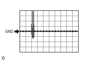
(e) Using an oscilloscope, check waveform 1.
NOTICE:
The oscilloscope waveform shown in the illustration is an example for reference only. Noise, chattering, etc. are not shown.
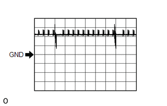 Waveform 1 (Reference)
|
Item |
Content |
|---|---|
|
Tester Connection |
M67-17 (CLG1) - F1-18 (E) M67-15 (CLG2) - F1-18 (E) |
|
Tool Setting |
5 V/DIV., 500 ms/DIV. |
|
Condition |
Procedure:
|
- *: For details about the entry function detection area, refer to Operation
Check.
Click here
(f) Using an oscilloscope, check waveform 2.
NOTICE:
The oscilloscope waveform shown in the illustration is an example for reference only. Noise, chattering, etc. are not shown.
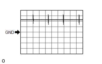 Waveform 2 (Reference)
|
Item |
Content |
|---|---|
|
Tester Connection |
M67-17 (CLG1) - F1-18 (E) M67-15 (CLG2) - F1-18 (E) |
|
Tool Setting |
5 V/DIV., 100 ms/DIV. |
|
Condition |
Procedure:
|
- *: For details about the entry function detection area, refer to Operation
Check.
Click here
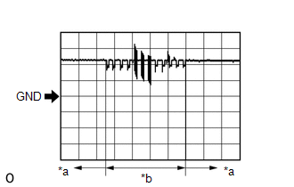
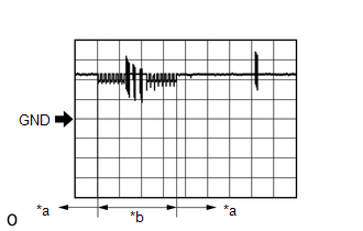
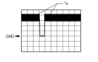
(g) Using an oscilloscope, check waveform 3.
NOTICE:
The oscilloscope waveform shown in the illustration is an example for reference only. Noise, chattering, etc. are not shown.
|
*a |
Lock sensor not touched |
|
*b |
Lock sensor touched |
|
Item |
Content |
|---|---|
|
Tester Connection |
M67-17 (CLG1) - F1-18 (E) M67-15 (CLG2) - F1-18 (E) |
|
Tool Setting |
5 V/DIV., 40 ms/DIV. |
|
Condition |
Procedure:
|
- *: For details about the entry function detection area, refer to Operation
Check.
Click here
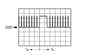
(h) Using an oscilloscope, check waveform 4.
NOTICE:
The oscilloscope waveform shown in the illustration is an example for reference only. Noise, chattering, etc. are not shown.
|
*a |
Unlock sensor not touched |
|
*b |
Unlock sensor touched |
|
Item |
Content |
|---|---|
|
Tester Connection |
M67-17 (CLG1) - F1-18 (E) M67-15 (CLG2) - F1-18 (E) |
|
Tool Setting |
5 V/DIV., 50 ms/DIV. |
|
Condition |
Procedure:
|
(i) Using an oscilloscope, check waveform 5.
NOTICE:
The oscilloscope waveform shown in the illustration is an example for reference only. Noise, chattering, etc. are not shown.
 Waveform 5 (Reference)
|
Item |
Content |
|---|---|
|
Tester Connection |
M67-16 (CG1B) - F1-18 (E) M67-14 (CG2B) - F1-18 (E) |
|
Tool Setting |
5 V/DIV., 500 ms/DIV. |
|
Condition |
Procedure:
|
- *: For details about the entry function detection area, refer to Operation
Check.
Click here
(j) Using an oscilloscope, check waveform 6.
NOTICE:
The oscilloscope waveform shown in the illustration is an example for reference only. Noise, chattering, etc. are not shown.
 Waveform 6 (Reference)
|
Item |
Content |
|---|---|
|
Tester Connection |
M67-16 (CG1B) - F1-18 (E) M67-14 (CG2B) - F1-18 (E) |
|
Tool Setting |
5 V/DIV., 100 ms/DIV. |
|
Condition |
Procedure:
|
- *: For details about the entry function detection area, refer to Operation
Check.
Click here
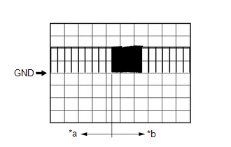
(k) Using an oscilloscope, check waveform 7.
NOTICE:
The oscilloscope waveform shown in the illustration is an example for reference only. Noise, chattering, etc. are not shown.
|
*a |
For 30 seconds after any door closed |
|
*b |
After 30 seconds or more have elapsed since any door closed |
|
Item |
Content |
|---|---|
|
Tester Connection |
F1-8 (CLG5) - F1-18 (E) F1-9 (CG5B) - F1-18 (E) M67-11 (CLG7) - F1-18 (E) M67-10 (CG7B) - F1-18 (E) |
|
Tool Setting |
2 V/DIV., 500 ms/DIV. |
|
Condition |
Procedure:
|
(l) Using an oscilloscope, check waveform 8.
NOTICE:
The oscilloscope waveform shown in the illustration is an example for reference only. Noise, chattering, etc. are not shown.
 Waveform 8 (Reference)
|
Item |
Content |
|---|---|
|
Tester Connection |
M67-13 (CLG8) - F1-18 (E) M67-12 (CG8B) - F1-18 (E) |
|
Tool Setting |
2 V/DIV., 500 ms/DIV. |
|
Condition |
Procedure:
|
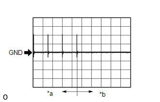
(m) Using an oscilloscope, check waveform 9.
NOTICE:
The oscilloscope waveform shown in the illustration is an example for reference only. Noise, chattering, etc. are not shown.
|
*a |
Checking for switch on signal at short intervals |
|
Item |
Content |
|---|---|
|
Tester Connection |
M67-26 (TSW5) - F1-18 (E) |
|
Tool Setting |
2 V/DIV., 500 ms/DIV. |
|
Condition |
Back door opener switch assembly (open switch) off → on |
|
Item |
Content |
|---|---|
|
Tester Connection |
M67-27 (TSW6) - F1-18 (E) |
|
Tool Setting |
2 V/DIV., 500 ms/DIV. |
|
Condition |
Back door opener switch assembly (lock switch) off → on |
(n) Using an oscilloscope, check waveform 10.
NOTICE:
The oscilloscope waveform shown in the illustration is an example for reference only. Noise, chattering, etc. are not shown.
|
*a |
Before lock or unlock switch of electrical key transmitter sub-assembly pressed |
|
*b |
After lock or unlock switch of electrical key transmitter sub-assembly pressed |
|
Item |
Content |
|---|---|
|
Tester Connection |
M67-18 (RCO) - F1-18 (E) |
|
Tool Setting |
2 V/DIV., 500 ms/DIV. |
|
Condition |
Procedure:
|
(o) Using an oscilloscope, check waveform 11.
NOTICE:
The oscilloscope waveform shown in the illustration is an example for reference only. Noise, chattering, etc. are not shown.
|
*a |
Before lock or unlock switch of electrical key transmitter sub-assembly pressed |
|
*b |
After lock or unlock switch of electrical key transmitter sub-assembly pressed |
|
Item |
Content |
|---|---|
|
Tester Connection |
M67-19 (RDAM) - F1-18 (E) |
|
Tool Setting |
5 V/DIV., 500 ms/DIV. |
|
Condition |
Procedure:
|
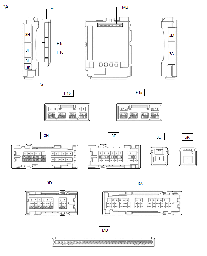
|
*A |
Main Body ECU (Multiplex Network Body ECU) with 2 Connectors |
- |
- |
|
*1 |
Main Body ECU (Multiplex Network Body ECU) |
- |
- |
|
*a |
2 Connectors |
- |
- |
|
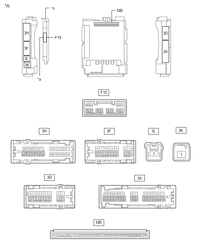
*A |
Main Body ECU (Multiplex Network Body ECU) with 1 Connector |
- |
- |
|
*1 |
Main Body ECU (Multiplex Network Body ECU) |
- |
- |
|
*a |
1 Connector |
- |
- |
CHECK MAIN BODY ECU (MULTIPLEX NETWORK BODY ECU) AND INSTRUMENT PANEL JUNCTION BLOCK ASSEMBLY
(a) Remove the main body ECU (multiplex network body ECU) from the instrument panel junction block assembly.
Click here
(b) Reconnect the instrument panel junction block assembly connectors.
(c) Measure the resistance and voltage according to the value(s) in the table below.
HINT:
Measure the values on the wire harness side with the connector disconnected.
|
Terminal No. (Symbol) |
Input/Output |
Wiring Color |
Terminal Description |
Condition |
Specified Condition |
Related Data List Item |
|---|---|---|---|---|---|---|
|
MB-11 (GND1) - Body ground |
- |
- |
Ground |
Always |
Below 1 Ω |
- |
|
MB-31 (BECU) - Body ground |
Input |
- |
Battery power supply (for CPU) |
Always |
11 to 14 V |
- |
|
F15-6 (FLCY) - Body ground |
Input |
R - Body ground |
Front door courtesy light switch assembly LH input |
Front door LH closed |
10 kΩ or higher |
FL Door Courtesy SW |
|
Front door LH open |
Below 1 Ω |
|||||
|
F15-27 (FRCY) - Body ground |
Input |
BR - Body ground |
Front door courtesy light switch assembly RH input |
Front door RH closed |
10 kΩ or higher |
FR Door Courtesy SW |
|
Front door RH open |
Below 1 Ω |
|||||
|
MB-13 (LCTY) - Body ground |
Input |
- |
Rear door courtesy light switch assembly LH input |
Rear door LH closed |
10 kΩ or higher |
RL Door Courtesy SW |
|
Rear door LH open |
Below 1 Ω |
|||||
|
MB-2 (RCTY) - Body ground |
Input |
- |
Rear door courtesy light switch assembly RH input |
Rear door RH closed |
10 kΩ or higher |
RR Door Courtesy SW |
|
Rear door RH open |
Below 1 Ω |
|||||
|
MB-4 (BCTY) - Body ground |
Input |
- |
Back door courtesy light switch input |
Back door closed |
10 kΩ or higher |
Back Door Courtesy SW |
|
Back door open |
Below 1 Ω |
(d) Install the main body ECU (multiplex network body ECU) to instrument panel junction block assembly.
Click here
(e) Measure the voltage and check for pulses according to the value(s) in the table below.
|
Tester Connection |
Input/Output |
Wiring Color |
Terminal Description |
Condition |
Specified Condition |
Related Data List Item |
|---|---|---|---|---|---|---|
|
3D-13 (LSFL) - Body ground |
Input |
B - Body ground |
Front door LH unlock detection switch input |
Front door LH locked → unlocked |
Pulse generation (See waveform 1) |
FL Door Lock Pos |
|
3D-12 (LSFR) - Body ground |
Input |
GR - Body ground |
Front door RH unlock detection switch input |
Front door RH locked → unlocked |
Pulse generation (See waveform 1) |
FR Door Lock Pos |
|
3D-14 (LSR) - Body ground |
Input |
LG - Body ground |
Rear door LH and Rear door RH unlock detection switch input |
Rear door LH and Rear door RH locked → Rear door LH or Rear door RH unlocked |
Pulse generation (See waveform 1) |
RL-Door Lock Pos SW RR-Door Lock Pos SW |
|
F15-6 (FLCY) - Body ground |
Input |
R - Body ground |
Front door LH courtesy light switch input |
Front door LH closed → open |
Pulse generation (See waveform 2) |
FL Door Courtesy SW |
|
F15-27 (FRCY) - Body ground |
Input |
BR - Body ground |
Front door RH courtesy light switch input |
Front door RH closed → open |
Pulse generation (See waveform 2) |
FR Door Courtesy SW |
|
3H-24 (LCTY) - Body ground |
Input |
BR - Body ground |
Rear door LH courtesy light switch input |
Rear door LH closed → open |
Pulse generation (See waveform 2) |
RL Door Courtesy SW |
|
3A-31 (RCTY) - Body ground |
Input |
BR - Body ground |
Rear door RH courtesy light switch input |
Rear door RH closed → open |
Pulse generation (See waveform 2) |
RR Door Courtesy SW |
|
3H-34 (BCTY) - Body ground |
Input |
SB - Body ground |
Back door courtesy light switch input |
Back door closed → opened |
Pulse generation (See waveform 2) |
Back Door Courtesy SW |
|
3F-29 (BZR) - Body ground |
Output |
L - Body ground |
Wireless buzzer signal output |
Procedure:
|
Below 1 V → pulse generation |
- |
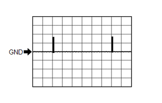
(f) Using an oscilloscope, check waveform 1.
NOTICE:
The oscilloscope waveform shown in the illustration is an example for reference only. Noise, chattering, etc. are not shown.
Waveform 1 (Reference)|
Item |
Content |
|---|---|
|
Tester Connection |
3D-13 (LSFL) - Body ground 3D-12 (LSFR) - Body ground 3D-14 (LSR) - Body ground |
|
Tool Setting |
2 V/DIV., 200 ms/DIV. |
|
Condition |
Door locked → unlocked |

|
*a |
Door locked |
|
*b |
Door unlocked |
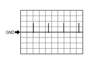
(g) Using an oscilloscope, check waveform 2.
NOTICE:
The oscilloscope waveform shown in the illustration is an example for reference only. Noise, chattering, etc. are not shown.
Waveform 2 (Reference)|
Item |
Content |
|---|---|
|
Tester Connection |
F15-6 (FLCY) - Body ground F15-27 (FRCY) - Body ground 3H-24 (LCTY) - Body ground 3A-31 (RCTY) - Body ground 3H-34 (BCTY) - Body ground |
|
Tool Setting |
2 V/DIV., 200 ms/DIV. |
|
Condition |
Door closed → opened |
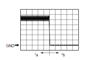
|
*a |
Door closed |
|
*b |
Door open |
 Problem Symptoms Table
PROBLEM SYMPTOMS TABLE
HINT:
If a problem occurs in certain locations or at certain times of day,
check for the possibility of wave interference.
When the electrical key transmitter ...
 Diagnosis System
DIAGNOSIS SYSTEM
DESCRIPTION
(a) Smart key system (for Entry Function) data and Diagnostic Trouble Codes (DTCs)
can be read through the vehicle Data Link Connector 3 (DLC3). In some cases, a malfu ...
Other materials:
Toyota CH-R Service Manual > Brake Fluid: On-vehicle Inspection
ON-VEHICLE INSPECTION
PROCEDURE
1. INSPECT BRAKE FLUID LEVEL IN RESERVOIR
(a) Check the fluid level.
If brake fluid level is lower than the MIN line, check for leaks and
inspect the disc brake pads. If necessary, refill the reservoir with brake
fluid to the MAX line after re ...
Toyota CH-R Service Manual > Audio And Visual System(for Radio And Display Type): Certification ECU Vehicle Information Reading/Writing Process Malfunction (B15F7)
DESCRIPTION
This DTC is stored when items controlled by the certification ECU (smart key
ECU assembly) cannot be customized via the audio and visual system vehicle customization
screen.
HINT:
The certification ECU (smart key ECU assembly) controls the smart key system
related items that are ...
Toyota C-HR (AX20) 2023-2026 Owner's Manual
Toyota CH-R Owners Manual
- For safety and security
- Instrument cluster
- Operation of each component
- Driving
- Interior features
- Maintenance and care
- When trouble arises
- Vehicle specifications
- For owners
Toyota CH-R Service Manual
- Introduction
- Maintenance
- Audio / Video
- Cellular Communication
- Navigation / Multi Info Display
- Park Assist / Monitoring
- Brake (front)
- Brake (rear)
- Brake Control / Dynamic Control Systems
- Brake System (other)
- Parking Brake
- Axle And Differential
- Drive Shaft / Propeller Shaft
- K114 Cvt
- 3zr-fae Battery / Charging
- Networking
- Power Distribution
- Power Assist Systems
- Steering Column
- Steering Gear / Linkage
- Alignment / Handling Diagnosis
- Front Suspension
- Rear Suspension
- Tire / Wheel
- Tire Pressure Monitoring
- Door / Hatch
- Exterior Panels / Trim
- Horn
- Lighting (ext)
- Mirror (ext)
- Window / Glass
- Wiper / Washer
- Door Lock
- Heating / Air Conditioning
- Interior Panels / Trim
- Lighting (int)
- Meter / Gauge / Display
- Mirror (int)
- Power Outlets (int)
- Pre-collision
- Seat
- Seat Belt
- Supplemental Restraint Systems
- Theft Deterrent / Keyless Entry

0.008