Toyota CH-R Service Manual: System Description
SYSTEM DESCRIPTION
MULTI CHANNEL FUNCTION
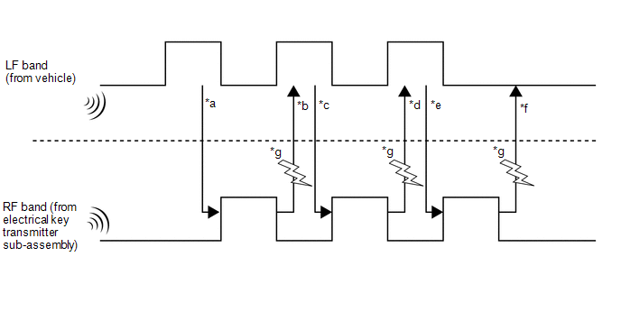
(a) The electrical key transmitter sub-assembly and electrical key and TPMS receiver assembly can operate on two different RF channels. When an electrical key transmitter sub-assembly is brought within an exterior detection area, key verification begins. If key verification fails due to wave interference, the channel will be switched and key verification will be performed again.
The multi channel system begins verification using the channel on which the last verification was successfully performed. When verification fails, the system switches to the other channel.
|
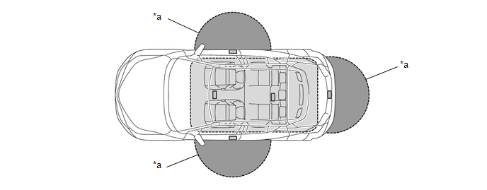
*a |
Exterior detection areas are created using LF waves (emitted from the vehicle at intervals of 0.25 seconds) to receive a response from the electrical key transmitter sub-assembly. |
*b |
When the electrical key transmitter sub-assembly is brought into an exterior detection area, it receives LF waves from the vehicle. Using RF waves, the electrical key transmitter sub-assembly responds to the vehicle. |
|
*c |
Upon receiving the response from the electrical key transmitter sub-assembly, the certification ECU (smart key ECU assembly) activates the electrical key antennas (outside) one by one. Using LF waves, the certification ECU (smart key ECU assembly) determines which exterior detection area the electrical key transmitter sub-assembly is in. |
*d |
The electrical key transmitter sub-assembly receives the LF waves from the vehicle and responds using RF waves. (The certification ECU (smart key ECU assembly) recognizes which exterior detection area the electrical key transmitter sub-assembly is in.) |
|
*e |
The certification ECU (smart key ECU assembly) sends registered key ID information to the electrical key transmitter sub-assembly using LF waves. (Up to 7 key IDs can be registered.) |
*f |
The electrical key transmitter sub-assembly sends the key ID information using RF waves. When the certification ECU (smart key ECU assembly) receives it, verification completes. |
|
*g |
Wave interference (Channel switching) |
- |
- |
The multi channel system changes the channels when the RF band (*b, *d and *f) is interrupted by wave interference. Refer to the table below to confirm when the system changes the channels.
|
*b or *d is NG |
*f is NG |
|||
|---|---|---|---|---|
|
Condition |
RF waves cannot be received |
RF waves cannot be received properly |
RF waves cannot be received |
RF waves cannot be received properly |
|
Channel switching |
The channels will not be switched. |
The channels will be switched. |
The channels will not be switched. |
The channels will be switched*. |
- *: The channels are not switched during vehicle interior verification after an entry lock operation is performed.
SMART KEY SYSTEM SPECIFICATIONS
(a) Some customers may inquire about the frequency used by the smart key system on various models. This repair manual contains the applicable specifications of the smart key system.
|
*a |
Transmitter Detection Area |
- |
- |
|
Specification |
||||
|---|---|---|---|---|
|
Frequency |
Output Power/Electric Field Intensity |
Modulation Method |
Mounting Point in Vehicle |
|
|
Inside Passenger Compartment |
134.2 kHz |
94.4 dBuV/m at 3 m |
AM |
Inside vehicle |
|
Outside Vehicle |
134.2 kHz |
95 dBuV/m at 3 m |
AM |
Inside door handle |
|
95 dBuV/m at 3 m |
AM |
Inside rear bumper |
||
|
Transmission Timing |
|||
|---|---|---|---|
|
Vehicle Remains Parked |
Entering or Exiting the Vehicle |
Vehicle is being Driven |
|
|
Inside Passenger Compartment |
Does not transmit |
|
When electrical key transmitter sub-assembly is not detected inside cabin while vehicle is being driven (transmits for 4 seconds) |
|
Outside Vehicle |
(1) When door is locked, transmits at 250 ms intervals (stops when door is unlocked) (2) Does not transmit |
(1) Touch the lock sensor (2) Pressing back door opener switch assembly (3) Touching unlock sensor in power saving mode |
Does not transmit |
BASIC PRECAUTIONS
(a) DTCs and Data Lists of ECUs related to the smart key system can be checked using the Techstream.
(b) Check for DTCs using the following procedure. If any DTCs are output, diagnose those DTCs first.
(1) Connect the Techstream to the DLC3.
(2) Turn the engine switch on (IG).
(3) Enter the following menus: Body Electrical / Smart Key, Power Source Control or Starting Control / Trouble Codes.
(c) When using the Techstream with the engine switch off, connect the Techstream to the DLC3 and turn a courtesy light switch on and off at intervals of 1.5 seconds or less until communication between the Techstream and the vehicle begins. Then select the vehicle type under manual mode and enter the following menus: Body Electrical / Smart Key. While using the Techstream, periodically turn a courtesy light switch on and off at intervals of 1.5 seconds or less to maintain communication between the Techstream and the vehicle.
(d) If the smart key system has been canceled by a customize setting, enable the smart key system.
Click here .gif)
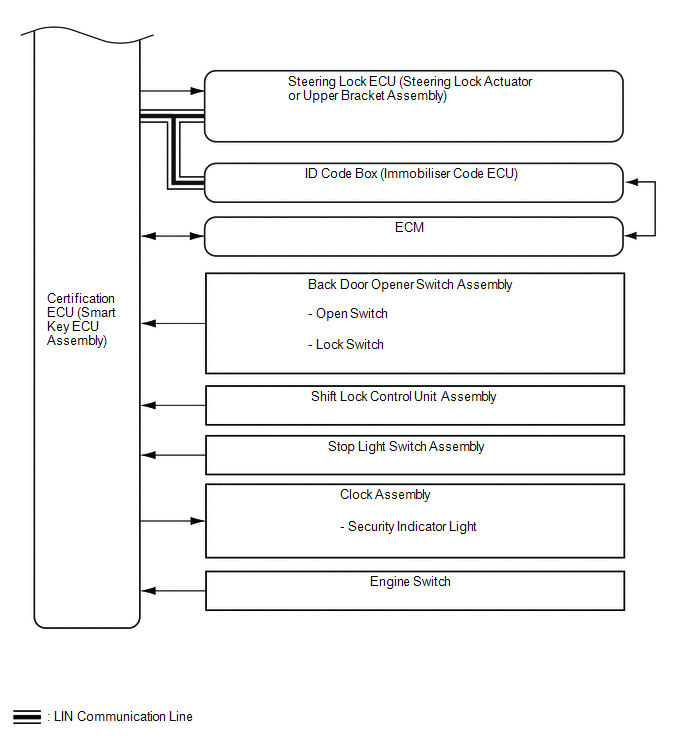
DIAGRAM OF SMART KEY SYSTEM
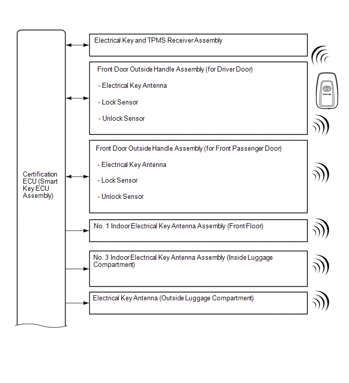
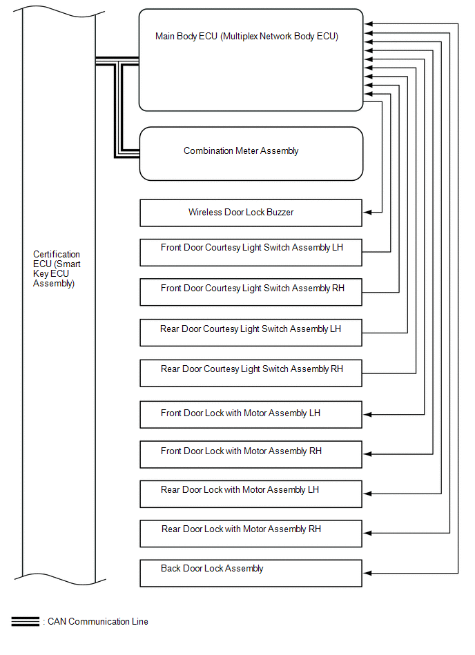
SYSTEM DESCRIPTION
The following pattern will be used: "Operation" indicates user operation using the smart key system. "Expected operation of the vehicle" indicates how a known good vehicle will react in accordance with each operation. "Suspected Area/Diagnosis" indicates suspected malfunctioning areas and tips for performing diagnosis if the vehicle did not react as expected.
(a) Example: Operation No.
|
Operation |
- |
|
Expected operation of the vehicle |
- |
|
Waveform or Output Value |
- |
|
Suspected Area |
Diagnosis |
|---|---|
|
- |
- |
DIAGNOSIS IN ACCORDANCE WITH USER OPERATION
(a) Operation 1
|
Operation |
Turn the engine switch off and lock all the doors, then take the electrical key transmitter sub-assembly approximately 3 m (9.84 ft.) or more away from the vehicle. HINT: The detection area of each electrical key antenna (outside) is formed by emitting a periodic LF band request signal every 0.25 seconds. The detection area formed by each front door outside handle assembly (electrical key antenna) has a detection range of approximately 0.7 m (2.30 ft.). |
|
Waveform or Output Value |
Pulse generation (M66-17 (CLG1) - F1-18 (E)*1) |
- *1: Click here
(b) Operation 2
|
Operation |
Bring the electrical key transmitter sub-assembly within 0.7 m (2.30 ft.) of the driver door. HINT: The system will enter in unlock standby mode when the electrical key transmitter sub-assembly is brought into the detection area and the key ID code sent by the electrical key transmitter sub-assembly matches the key ID code stored by the certification ECU (smart key ECU assembly). The door unlocks if the unlock sensor is touched by hand with the system in unlock standby mode. Signal transmission: Certification ECU (smart key ECU assembly) → Door outside handle assembly (electrical key antenna) → Electrical key transmitter sub-assembly → Electrical key and TPMS receiver assembly → Certification ECU (smart key ECU assembly) → Main body ECU (multiplex network body ECU) |
|
Expected operation of the vehicle |
The LED of the electrical key transmitter sub-assembly starts blinking. If it does not, check the suspected areas in the following table. |
|
Waveform or Output Value |
|
- *1: Click here
|
Suspected Area |
Diagnosis |
|---|---|
|
Electrical key transmitter sub-assembly |
HINT:
|
|
Transmitter battery is depleted |
|
|
Wave Interference |
|
|
Certification ECU (smart key ECU assembly) |
- |
|
Main body ECU (multiplex network body ECU) |
- |
|
Front door outside handle assembly |
Vehicle exterior detection area is not formed properly.
|
|
Electrical key and TPMS receiver assembly |
|
|
Battery is discharged |
It may be possible to tell whether the battery is discharged by operating the horn. |
|
Others |
|
(c) Operation 3
|
Operation |
Touch the unlock sensor of the front door outside handle assembly LH with the electrical key transmitter sub-assembly in the exterior detection area. |
|
Expected operation of the vehicle |
While the doors are unlocked, the answer-back is performed at the same time. If they do not, check the suspected areas in the following table. |
|
Waveform or Output Value |
|
- *1: Click here
|
Suspected Area |
Diagnosis |
|---|---|
|
The suspected parts below overlap with the parts covered in operation 2 for when the LED of the electrical key transmitter sub-assembly does not blink. |
- |
|
Front door outside handle assembly (unlock sensor) |
|
|
Door lock/unlock mechanism |
If a door cannot be locked/unlocked by operating the door control switch on the door in the cabin, the door lock mechanism is malfunctioning. |
(d) Operation 4
|
Operation |
After getting into the vehicle while carrying the electrical key transmitter sub-assembly, close the door and press the engine switch once with the shift lever in P while not depressing the brake pedal. |
|
Expected operation of the vehicle |
If any of the preceding do not happen, check the suspected areas in the following table. HINT: When the engine switch is pressed, the indoor electrical key antennas form the key detection area inside the vehicle and detect the electrical key transmitter sub-assembly in the cabin. The electrical key transmitter sub-assembly sends a key ID code upon receiving a request signal and the LED of the electrical key transmitter sub-assembly illuminates for a short time. After pressing the engine switch, if the key ID code sent by the electrical key transmitter sub-assembly matches the key ID code stored by the certification ECU (smart key ECU assembly), the ACC relay turns on and entry warning light is displayed on the multi-information display in the combination meter assembly. After the power source mode has changed, and L code and S code verification has been completed, the steering will be unlocked and the immobiliser will be disabled. The Data List item "Immobiliser" will then change from "Set" to "Unset". Signal transmission: Certification ECU (smart key ECU assembly) → Indoor electrical key antenna → Electrical key transmitter sub-assembly → Electrical key and TPMS receiver assembly → Certification ECU (smart key ECU assembly) HINT: The interior detection area is formed when any of the following conditions are met:
|
|
Waveform or Output Value |
|
- *1: Click here
|
Suspected Area |
Diagnosis |
|---|---|
|
Certification ECU (smart key ECU assembly) |
- |
|
Wave Interference |
|
|
Indoor electrical key antenna assemblies that form the interior detection areas |
|
|
Engine switch |
Under normal conditions, after the engine switch is pressed, "ON" is displayed for the Data List items "Start Switch1" and "Start Switch2". |
|
ID code box (immobiliser code ECU) |
In order to unlock the steering, it is necessary for "OK" to be displayed for the Data List item "S Code Check". If "OK" is displayed for "S Code Check", the certification ECU (smart key ECU assembly) code and ID code box (immobiliser code ECU) code match. |
|
Park/neutral position switch |
Under normal conditions "ON" is displayed for the Data List item, "Neutral SW/ Clutch SW" when the shift lever is in P. |
|
Steering lock ECU (steering lock actuator or upper bracket assembly) |
|
(e) Operation 5
|
Operation |
Depress the brake pedal with the shift lever in P while carrying an electrical key transmitter sub-assembly. |
|
Expected operation of the vehicle |
The entry warning light appears on the multi-information display. If it does not, check the suspected areas in the following table. |
|
Suspected Area |
Diagnosis |
|---|---|
|
Stop light switch assembly |
If the brake pedal is depressed, "ON" is displayed for the Data List item "Stop Light Switch1". |
|
Certification ECU (smart key ECU assembly) |
Start function-Terminals of ECU Click here |
(f) Operation 6
|
Operation |
After getting into the vehicle while carrying the electrical key transmitter sub-assembly, press the engine switch with the shift lever in P while depressing the brake pedal. |
|
Expected operation of the vehicle |
The engine starts. If it does not, check the suspected areas in the following table. |
|
Suspected Area |
Diagnosis |
|---|---|
|
Steering lock system |
Under normal conditions, the steering will be unlocked and "ON" will be displayed for the Data List item "Steering Unlock Switch". |
|
Battery is discharged |
Whether the battery is discharged or not can be checked easily by operating the horn. |
(g) Operation 7
|
Operation |
With the engine running, press the engine switch. |
|
Expected operation of the vehicle |
The engine stops, the entry warning light illuminates and then turns off and the security indicator light changes from off to blinking. |
(h) Operation 8
|
Operation |
Turn the engine switch off and open any of the doors. |
|
Expected operation of the vehicle |
The steering locks. If it does not, check the suspected areas in the following table. |
|
Suspected Area |
Diagnosis |
|---|---|
|
Steering lock system |
- |
|
Door courtesy light switch assembly |
When the driver door is opened, "ON" is displayed for the Data List item "FL Door Courtesy SW". |
(i) Operation 9
|
Operation |
Touch the lock sensor of the front door outside handle assembly LH while carrying the electrical key transmitter sub-assembly. |
|
Expected operation of the vehicle |
The door lock and the answer-back is performed simultaneously. |
BATTERY SAVING FUNCTION
(a) When the smart key system is operating, the vehicle performs key detection operations every 0.25 seconds. Therefore, if the vehicle is left as is for a long period of time, the battery may become fully discharged. The following controls help reduce the rate at which the battery is discharged.
(1) If the smart key system is not operated for 5 days or more, periodic signal transmission from the electrical key antennas stops. However, the doors can still be unlocked by touching the unlock sensor of a front door outside handle assembly.
(2) If the smart key system is not operated for 14 days or more, the lock and unlock sensors of the front door outside handle assembly RH will be disabled. Therefore, only the unlock sensor of the front door outside handle assembly LH can be used to unlock the doors.
(3) If 10 minutes or more elapse while the electrical key transmitter sub-assembly is in an exterior detection area, the front door outside handle assembly (electrical key antenna) detecting the electrical key transmitter sub-assembly will stop operating.
(b) To restore operation of the smart key system, perform any of the following operations.
(1) While carrying the electrical key transmitter sub-assembly, touch the lock or unlock sensor of the front door outside handle assembly LH and perform a door lock or unlock operation.
(2) Lock or unlock the doors using the wireless function.
(3) Insert the mechanical key into the door key cylinder of the driver door and lock or unlock the doors.
WIRELESS BUZZER VOLUME ADJUSTMENT FUNCTION (w/ Toyota Safety Sense P)
(a) The volume of the wireless buzzer can be changed through the customize function.
HINT:
The volume of the following wireless buzzer operations cannot be adjusted.
- Warning function buzzer operations
- Customize function buzzer operations
- Buzzer operations for key diagnostic mode using the Techstream
- Key registration buzzer operations
WARNING FUNCTION
(a) Warning
(1) Situation: The engine is left running and the shift lever is in a position other than P when the driver gets out of the vehicle.
- There are 2 patterns for this situation.
- Pattern 1:
When the engine is left running and the shift lever is in a position other than P, the driver opens the door and attempts to get out of the vehicle.
In this situation, the following control is performed:
Reason for warning
Prevention of sudden acceleration, vehicle theft deterrent, prevention of vehicle roll-away
Warning Start Condition
(All conditions are met)
- The engine switch is on (ACC) or on (IG).
- The shift lever is in a position other than P.
- The driver door is opened.
- No vehicle speed is detected.
Warning description
- The buzzer in the combination meter assembly sounds continuously.
- "Shift to P Before Exiting Vehicle" is displayed on the multi-information display in the combination meter assembly.
Warning Stop Condition
(One condition is met)
- The engine switch is turned off.
- The shift lever is in P.
- The driver door is closed.
- The vehicle speed is 5 km/h (3 mph) or more.
- Pattern 2:
Under the situation of pattern 1, the driver closes the door and attempts to leave the vehicle while holding the electrical key transmitter sub-assembly.
In this situation, the following control is performed:
Reason for warning
Prevention of sudden acceleration, vehicle theft deterrent, prevention of vehicle roll-away
Warning Start Condition
(All conditions are met)
- The engine switch is on (ACC) or on (IG).
- The shift lever is in a position other than P.
- The driver door is opened → closed.
- The electrical key transmitter sub-assembly is not in the vehicle.
- No vehicle speed is detected.
Warning description
- The buzzer in the combination meter assembly sounds continuously.
- The wireless buzzer sounds continuously.
- "Shift to P Before Exiting Vehicle"(A) and "Key Not Detected Check Key Location"(B) are displayed alternately on the multi-information display in the combination meter assembly.
Warning Stop Condition
(One condition is met)
Warning stop conditions for (A)
- The shift lever is in P.
- The vehicle speed is 5 km/h (3 mph).
Warning stop conditions for (B)
- The engine switch is turned off.
- The electrical key transmitter sub-assembly is returned to the vehicle.
- Pattern 1:
(2) Situation: The key reminder sounds.
- There are 3 patterns for this situation.
- Pattern 1:
When the shift lever is in P and the steering is unlocked, the driver opens the door and attempts to get out of the vehicle.
In this situation, the following control is performed:
Reason for warning
Vehicle theft deterrent
Warning Start Condition
(Warning starts when condition 1 is met or condition 2 is met for 1 second)
Condition 1
- The engine switch is on (ACC).
- The driver door is opened.
Condition 2
- The engine switch is off.
- The steering is unlocked.
- The driver door is opened.
Warning description
- The buzzer in the combination meter assembly sounds continuously at short and even intervals.
Warning Stop Condition
(One condition is met)
- The engine switch is turned on (IG).
- The driver door is closed.
- The engine switch is turned off and the steering is locked.
- Pattern 2:
Under the situation of pattern 1, the driver closes the driver door and attempts to leave the vehicle while carrying the electrical key transmitter sub-assembly.
In this situation, the following control is performed:
Reason for warning
Vehicle theft deterrent
Warning Start Condition
(All conditions are met)
- The engine switch is on (ACC) or on (IG).
- The shift lever is in P.
- The driver door is opened → closed.
- The electrical key transmitter sub-assembly is not in the vehicle.
- No vehicle speed is detected.
Warning description
- The buzzer in the combination meter assembly sounds once.
- The wireless buzzer sounds 3 times.
- "Key Not Detected Check Key Location" is displayed on the multi-information display in the combination meter assembly.
Warning Stop Condition
(Either condition is met)
- The engine switch is turned off.
- The electrical key transmitter sub-assembly is returned to the vehicle.
- Pattern 3:
Under the situation of pattern 2, the driver touches the lock sensor on the door outside handle assembly.
In this situation, the following control is performed:
Reason for warning
Vehicle theft deterrent
Warning Start Condition
(All conditions are met)
- The engine switch is on (ACC) or on (IG).
- The shift lever is in P.
- The electrical key transmitter sub-assembly is not in the interior detection areas.
- The electrical key transmitter sub-assembly is in the exterior detection areas.
- The lock sensor is on.
- No vehicle speed is detected.
Warning description
- The buzzer in the combination meter assembly sounds once.
- The wireless buzzer sounds continuously.
- "Turn Power Off"(A) and "Key Not Detected Check Key Location"(B) are displayed alternately on the multi-information display in the combination meter assembly.
Warning Stop Condition
(One condition is met)
- 5 seconds have elapsed after the warning started (only wireless buzzer stops).
- Any door is opened (only wireless buzzer stops).
- Any door is closed (only wireless buzzer stops).
Warning stop conditions for (A)
- 60 seconds have elapsed after the warning started.
- The engine switch is off.
- The shift lever is in a position other than P.
- The vehicle speed is 5 km/h (3 mph).
Warning stop conditions for (B)
- The engine switch is off.
- The electrical key transmitter sub-assembly is returned to the vehicle.
- Pattern 1:
(3) Situation: A passenger gets out of the vehicle while carrying the electrical key transmitter sub-assembly.
- When the engine switch is on (ACC) or on (IG), a passenger opens a door
other than the driver door and attempts to get out of the vehicle while
holding the electrical key transmitter sub-assembly.
In this situation, the following control is performed:
Reason for warning
Preventing vehicle from becoming impossible to restart
Warning Start Condition
(All conditions are met)
- The engine switch is on (ACC) or on (IG).
- A door other than the driver door is opened → closed.
- The electrical key transmitter sub-assembly is not in the vehicle.
- No vehicle speed is detected.
Warning description
- The buzzer in the combination meter assembly sounds once.
- The wireless buzzer sounds 3 times.
- "Key Not Detected Check Key Location" is displayed on the multi-information display in the combination meter assembly.
Warning Stop Condition
(Either condition is met)
- The engine switch is turned off.
- The electrical key transmitter sub-assembly is returned to the vehicle.
(4) Situation: The electrical key transmitter sub-assembly is not in the interior or exterior detection areas.
- The driver attempts to turn the engine switch on (IG) when the electrical
key transmitter sub-assembly is not in the cabin, or attempts to change
the power source mode by touching the electrical key transmitter sub-assembly
to the engine switch.
In this situation, the following control is performed:
Reason for warning
User confusion prevention
Warning Start Condition
(All conditions are met)
- The immobiliser system is set.
- The electrical key transmitter sub-assembly is not in the vehicle or the transmitter battery is depleted. (Interior verification failed or verification failed when the transmitter battery is depleted and the electrical key transmitter sub-assembly was touched to the engine switch.)
- There is no history of unlocking the doors using the mechanical key and no history of verification failure when the engine switch is pressed.
Warning description
- The buzzer in the combination meter assembly sounds once.
- "Key Not Detected Check Key Location" is displayed on the multi-information display in the combination meter assembly.
Warning Stop Condition
(One condition is met)
- 15 seconds have elapsed after the warning started.
- The electrical key transmitter sub-assembly is returned to the vehicle. (Interior verification succeed or verification succeed when the transmitter battery is depleted and the electrical key transmitter sub-assembly was touched to the engine switch.)
- The driver door is opened using the door outside handle and 30 seconds have elapsed.
(5) Situation: The vehicle is driven without a registered electrical key transmitter sub-assembly.
- In this situation, the following control is performed:
Reason for warning
Preventing vehicle from becoming impossible to restart
Warning Start Condition
(All conditions are met)
- The engine switch is on (IG).
- Warning for when a passenger gets out of the vehicle while carrying the electrical key transmitter sub-assembly is operating.
- The vehicle speed is 5 km/h (3 mph) or more.
- The electrical key transmitter sub-assembly is not in the vehicle.
Warning description
- The buzzer in the combination meter assembly sounds nine times.
- "Key Not Detected Check Key Location" is displayed on the multi-information display in the combination meter assembly.
Warning Stop Condition
(Either condition is met)
- The electrical key transmitter sub-assembly is returned to the vehicle.
- The engine switch is turned off.
(6) Situation: The electrical key transmitter sub-assembly is left in the vehicle.
The lock sensor on a door outside handle assembly is touched to perform an entry lock operation with the electrical key transmitter sub-assembly left in the vehicle.
In this situation, the following control is performed:
|
Reason for warning |
Vehicle theft deterrent |
|
Warning Start Condition (All conditions are met) |
|
|
Warning description |
|
|
Warning Stop Condition (One condition is met) |
|
(7) Situation: Door is ajar.
- The lock sensor on a door outside handle assembly is touched to perform
an entry lock operation with a door open.
In this situation, the following control is performed:
Reason for warning
Vehicle theft deterrent
Warning Start Condition
(All conditions are met)
- The engine switch is off.
- Any door other than the door that locked using the entry lock function is open.
- The lock sensor is on or lock switch is pressed on the electrical key transmitter sub-assembly.
- The electrical key transmitter sub-assembly is in the exterior detection areas.
Warning description
- The wireless buzzer sounds continuously.
Warning Stop Condition
(One condition is met)
- 5 seconds have elapsed after the wireless buzzer is activated.
- The engine switch is on (ACC) or on (IG).
- All doors are closed.
- The doors are unlocked by a wireless door unlock operation.
- The doors are unlocked by a the entry unlock operation.
- Any of the doors are opened.
(8) Situation: The electrical key transmitter sub-assembly is locked inside the vehicle.
- The electrical key transmitter sub-assembly is locked inside the vehicle.
In this situation, the following control is performed:
Reason for warning
Vehicle theft deterrent
Warning Start Condition
Condition 1 (All conditions are met)
- With a door open, the lock knob is locked and then the door is closed with the door handle being pulled.
- The electrical key transmitter sub-assembly is in the vehicle.
- No vehicle speed is detected.
Condition 2 (All conditions are met)
- The engine switch is off.
- All doors are closed and locked.
- Lock operation other than entry lock operation is performed.
- The electrical key transmitter sub-assembly is inside vehicle (matching code is detected in vehicle interior).
Warning description
- The buzzer in the combination meter assembly sounds once.
- The wireless buzzer sounds continuously.
- "Key Detected in Vehicle" is displayed on the multi-information display in the combination meter assembly.
Warning Stop Condition
(One condition is met)
- 5 seconds have elapsed after the wireless buzzer is activated (only wireless buzzer stops).
- 60 seconds have elapsed after the warning started.
- The power source mode is changed to a mode other than off.
- Any door is opened (only wireless buzzer stops).
- The doors are locked.
- The vehicle speed is 5 km/h (3 mph) or more.
(9) Situation: The transmitter battery is weak.
- The vehicle is driven using an electrical key transmitter sub-assembly
that has a low transmitter battery.
In this situation, the following control is performed:
Reason for warning
Preventing vehicle from becoming impossible to restart, usability function
Warning Start Condition
(Either Condition 1 or 2 is met)
Condition 1 (All conditions are met)
- The engine switch is turned off after being left on (IG) for more than 20 minutes.
- The transmitter battery voltage is low.
- The electrical key transmitter sub-assembly is in the vehicle.
- No vehicle speed is detected.
Condition 2 (All conditions are met)
- The engine is off → the engine is started
- The transmitter battery voltage is low.
- The electrical key transmitter sub-assembly is in the vehicle.
- No vehicle speed is detected.
- Condition 1 has been met. (In the past)
Warning description
- The buzzer in the combination meter assembly sounds once.
- "Key Battery Low Replace Key Battery" is displayed on the multi-information display in the combination meter assembly.
Warning Stop Condition
(Either condition is met)
- 15 seconds have elapsed after the warning started.
- The vehicle speed is 5 km/h (3 mph) or more.
(10) Situation: The steering cannot be released.
- The steering cannot be released, thus the engine is prevented from starting.
The shift lever is moved to a position other than P before the steering is unlocked.
In this situation, the following control is performed:
Reason for warning
Usability function
Warning Start Condition
- Steering cannot be unlocked (judged by the steering lock ECU (steering lock actuator or upper bracket assembly)).
Warning description
- The buzzer in the combination meter assembly sounds once.
- "Push ENGINE Switch while Turning The Steering Wheel in Either Direction" is displayed on the multi-information display in the combination meter assembly.
Warning Stop Condition
(Either condition is met)
- 15 seconds have elapsed after the warning started.
- The steering is unlocked.
(11) Situation: The smart key system is malfunctioning.
- A malfunction that interferes with the steering lock ECU (steering lock
actuator or upper bracket assembly) or a vehicle speed signal malfunction
is detected.
In this situation, the following control is performed:
Reason for warning
Malfunction detection
Warning Start Condition
(One condition is met)
- The steering lock ECU (steering lock actuator or upper bracket assembly), certification ECU (smart key ECU assembly) or unlock detection switch is malfunctioning.
- The vehicle speed is judged as abnormal or vehicle speed signal communication is malfunctioning.
Warning description
- The buzzer in the combination meter assembly sounds once.
- "Smart Key System Malfunction See Owner's Manual" is displayed on the multi-information display in the combination meter assembly.
Warning Stop Condition
(Either condition is met)
- 15 seconds have elapsed after the warning started.
- The system returns to normal.
(12) Situation: The engine does not start. (Situation A)
- When the driver door is opened using the mechanical key and the engine
switch is pressed, the electrical key transmitter sub-assembly cannot be
detected in the vehicle, or when the engine switch is pressed, the electrical
key transmitter sub-assembly cannot be detected two times in a row.
In this situation, the following control is performed:
Reason for warning
Usability function
Warning Start Condition
(One condition is met)
- The immobiliser system is set.
- The electrical key transmitter sub-assembly is not in the vehicle.
- Key code verification error occurs when the engine switch is pressed twice or the driver door key-linked unlock operation is performed.
Warning description
- The buzzer in the combination meter assembly sounds once.
- ""Depress Brake Pedal and Touch ENGINE Switch with Key" is displayed on the multi-information display in the combination meter assembly.
Warning Stop Condition
(One condition is met)
- 60 seconds have elapsed after the warning started.
- The electrical key transmitter sub-assembly is in the vehicle. (Interior verification succeed or verification succeed when the transmitter battery is depleted and the electrical key transmitter sub-assembly was touched to the engine switch.)
- The driver door is opened using the front door outside handle assembly LH and 30 seconds have elapsed.
(13) Situation: Immobiliser system certification completion occurs.
- When the transmitter battery is depleted, the smart key system is canceled
or wave interference occurs, the electrical key transmitter sub-assembly
is touched to the engine switch.
In this situation, the following control is performed:
Reason for warning
Usability function
Warning Start Condition
- Electrical key transmitter sub-assembly certification result is OK.
Warning description
- The buzzer in the combination meter assembly sounds once.
- "Depress Brake Pedal & Push ENGINE Switch to Start" is displayed on the multi-information display in the combination meter assembly.
Warning Stop Condition
(One condition is met)
- 10 seconds have elapsed after the warning started.
- The electrical key transmitter sub-assembly is detected by the vehicle.
- The engine speed is at 500 rpm or more.
- The vehicle can be driven.
- The immobiliser system is set and key recognition is stopped or the key cannot be recognized.
(14) Situation: The engine does not start. (Situation B)
- There are two patterns for this situation.
- Pattern 1:
The engine might be started (when the driver gets in the vehicle, or the engine switch is turned on (ACC)).
In this situation, the following control is performed:
Reason for warning
Usability function
Warning Start Condition
(Either condition is met)
- After the doors are unlocked from outside the vehicle with the engine switch off, the driver door is opened.
- With the brake pedal not depressed, the engine switch is turned on (ACC).
Warning description
(Not displayed while the opening image is displayed.)
- "Depress Brake Pedal & Push ENGINE Switch to Start" is displayed on the multi-information display in the combination meter assembly.
Warning Stop Condition
(One condition is met)
- 19 seconds have elapsed after the warning started.
- The engine is started.
- The doors are locked from outside the vehicle.
- The doors are locked by a wireless door lock operation from inside the vehicle.
- Pattern 2:
The engine might be started (when the engine switch is on (IG)).
In this situation, the following control is performed:
Reason for warning
Usability function
Warning Start Condition
(Either condition is met)
- With the brake pedal not depressed, the engine switch is turned on (IG) (the engine is not started).
- The engine switch is on (IG) (the engine is not started) and the shift lever is moved from a position other than P or N to P or N.
Warning description
- "Not Ready to Drive Depress Brake Pedal & Push ENGINE Switch to Start" is displayed on the multi-information display in the combination meter assembly.
Warning Stop Condition
(One condition is met)
- The power source mode is changed to any mode other than on (IG).
- The vehicle speed is 5 km/h (3 mph) or more.
- The shift lever is moved to a position other than P or N.
- Pattern 1:
(15) Situation: The engine switch cannot be turned off.
- There are 2 patterns for this situation.
- Pattern 1:
A warning message appears on the multi-information display when the driver attempts to turn the engine switch off with the shift lever in any position other than P
In this situation, the following control is performed:
Reason for warning
Prevention of battery discharge, prevention of vehicle roll-away
Warning Start Condition
- The engine switch is turned off with the shift lever in a position other than P or N. (Excluding an emergency stop by pressing the engine switch 3 times quickly or pressing and holding the engine switch for 2 seconds or more.)
Warning description
- The buzzer in the combination meter assembly sounds once.
- "Shift to P Before Exiting Vehicle" is displayed on the multi-information display in the combination meter assembly.
Warning Stop Condition
(Either condition is met)
- The shift lever is moved to P.
- The power source mode is changed to a mode other than on (ACC).
- Pattern 2:
Under the situation of pattern 1, the shift lever is moved to P.
In this situation, the following control is performed:
Reason for warning
Prevention of battery discharge
Warning Start Condition
- The shift lever is moved to P.
Warning description
- The buzzer in the combination meter assembly sounds once.
- "Turn Power Off" is displayed on the multi-information display in the combination meter assembly.
Warning Stop Condition
(Either condition is met)
- The power source mode is changed to a mode other than on (ACC).
- The shift lever is in any position other than P.
- Pattern 1:
(16) Situation: Auto power off operation occurs.
- A warning message appears on the multi-information display when an automatic
power off operation occurs.
In this situation, the following control is performed:
Reason for warning
Usability function
Warning Start Condition
(All conditions are met)
- The shift lever is in P.
- The engine switch is on (ACC) or on (IG).
- No vehicle speed is detected and the engine is stopped.
- The power source mode is changed to off by automatic power off function. (20 minutes have elapsed with the engine switch on (ACC) or 1 hour has elapsed with the engine switch on (IG).)
Warning description
- "Auto Power Off to Conserve Battery" is displayed on the multi-information display in the combination meter assembly.
Warning Stop Condition
(Either condition is met)
- 10 seconds have elapsed after the warning started.
- The engine switch is turned on (ACC) or on (IG).
(17) Situation: An electrical key transmitter sub-assembly has been registered.
- A warning message appears on the multi-information display when an electrical
key transmitter sub-assembly has been registered to the vehicle.
In this situation, the following control is performed:
Reason for warning
Usability function
Warning Start Condition
(All conditions are met)
- The engine switch is off.
- The driver door is unlocked and opened.
- Within 10 days after a new key has been registered.
Warning description
- "A New Key has been Registered Contact Your Dealer for Details" is displayed on the multi-information display in the combination meter assembly.
Warning Stop Condition
(One condition is met)
- 60 seconds have elapsed after the warning started.
- All doors are closed and locked.
- The engine switch is on (IG).
(18) Situation: The shift lever is in a position other than P or N with the engine stopped.
- A warning message appears on the multi-information display when the
shift lever is in a position other than P or N while the engine switch is
on (ACC) or on (IG) and the engine is stopped.
In this situation, the following control is performed:
Reason for warning
Prevention of vehicle roll-away
Warning Start Condition
(All conditions are met)
- The engine switch is on (IG).
- No vehicle speed is detected.
- The shift lever is in a position other than P or N.
Warning description
- The buzzer in the combination meter assembly sounds once.
- "Engine Stopped Shift to Position" is displayed on the multi-information display in the combination meter assembly.
Warning Stop Condition
(One condition is met)
- The shift lever is moved to P or N.
- The engine switch is turned off.
- The vehicle speed is 5 km/h (3 mph) or more.
(19) Situation: The vehicle is moving with the engine switch on (IG) and the engine is stopped.
- A warning message appears on the multi-information display if the vehicle
begins moving when the engine switch is on (IG) and the engine is stopped.
In this situation, the following control is performed:
Reason for warning
Prevention of vehicle roll-away
Warning Start Condition
(All conditions are met)
- The engine switch is on (IG).
- The shift lever is in a position other than P or N.
- The engine is stopped.
- The vehicle speed is 2 km/h (1 mph) or more.
Warning description
- The buzzer in the combination meter assembly sounds continuously.
- "Engine Stopped Stop in a Safe Place" is displayed on the multi-information display in the combination meter assembly.
Warning Stop Condition
(One condition is met)
- The shift lever is moved to N.
- The engine switch is turned off.
- The engine is started.
- No vehicle speed is detected.
 How To Proceed With Troubleshooting
CAUTION / NOTICE / HINT
HINT:
Use these procedures to troubleshoot the smart key system (for Entry
Function).
*: Use the Techstream.
PROCEDURE
1.
VEHIC ...
 Operation Check
OPERATION CHECK
CHECK SMART KEY SYSTEM (for Entry Function) OPERATION
NOTICE:
Make sure that the smart key system (for Entry Function) has not been canceled
before performing this inspection.
(a ...
Other materials:
Toyota CH-R Service Manual > Condenser: Components
COMPONENTS
ILLUSTRATION
*A
w/o Engine Hood Courtesy Switch
*B
w/ Engine Hood Courtesy Switch
*1
FRONT BUMPER UPPER REINFORCEMENT SUB-ASSEMBLY
*2
HOOD LOCK ASSEMBLY
*3
NO. 1 A ...
Toyota CH-R Service Manual > Navigation System: "No GPS signal" mark is displayed
CAUTION / NOTICE / HINT
NOTICE:
Depending on the parts that are replaced during vehicle inspection or
maintenance, performing initialization, registration or calibration may
be needed. Refer to Precaution for Navigation System.
Click here
When replacing the radio ...
Toyota C-HR (AX20) 2023-2026 Owner's Manual
Toyota CH-R Owners Manual
- For safety and security
- Instrument cluster
- Operation of each component
- Driving
- Interior features
- Maintenance and care
- When trouble arises
- Vehicle specifications
- For owners
Toyota CH-R Service Manual
- Introduction
- Maintenance
- Audio / Video
- Cellular Communication
- Navigation / Multi Info Display
- Park Assist / Monitoring
- Brake (front)
- Brake (rear)
- Brake Control / Dynamic Control Systems
- Brake System (other)
- Parking Brake
- Axle And Differential
- Drive Shaft / Propeller Shaft
- K114 Cvt
- 3zr-fae Battery / Charging
- Networking
- Power Distribution
- Power Assist Systems
- Steering Column
- Steering Gear / Linkage
- Alignment / Handling Diagnosis
- Front Suspension
- Rear Suspension
- Tire / Wheel
- Tire Pressure Monitoring
- Door / Hatch
- Exterior Panels / Trim
- Horn
- Lighting (ext)
- Mirror (ext)
- Window / Glass
- Wiper / Washer
- Door Lock
- Heating / Air Conditioning
- Interior Panels / Trim
- Lighting (int)
- Meter / Gauge / Display
- Mirror (int)
- Power Outlets (int)
- Pre-collision
- Seat
- Seat Belt
- Supplemental Restraint Systems
- Theft Deterrent / Keyless Entry

0.0081