Toyota CH-R Service Manual: Parts Location
PARTS LOCATION
ILLUSTRATION
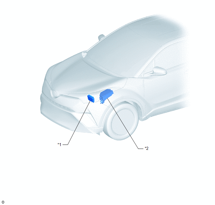
|
*1 |
ECM |
*2 |
NO. 1 ENGINE ROOM RELAY BLOCK |
ILLUSTRATION
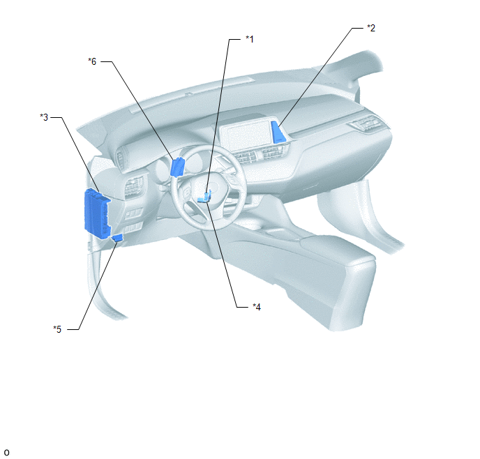
|
*1 |
UNLOCK WARNING SWITCH ASSEMBLY |
*2 |
SECURITY INDICATOR LIGHT (CLOCK ASSEMBLY) |
|
*3 |
INSTRUMENT PANEL JUNCTION BLOCK ASSEMBLY - ECU-IG2 NO. 3 FUSE - ECU-B NO. 1 FUSE |
*4 |
TRANSPONDER KEY COIL |
|
*5 |
DLC3 |
*6 |
TRANSPONDER KEY ECU ASSEMBLY |

 Precaution
PRECAUTION
PRECAUTIONS WHEN USING TECHSTREAM
(a) After all DTCs are cleared, check if the malfunction occurs again 6 seconds
after turning the ignition switch ON.
PRECAUTIONS FOR THE KEY
(a) The ...
Other materials:
Toyota CH-R Service Manual > Navigation System: Microphone Circuit
DESCRIPTION
The radio and display receiver assembly, map light assembly and telephone microphone
assembly are connected to each other using the microphone connection detection signal
lines.
Using this circuit, the DCM (telematics transceiver) sends power to the map light
assembly and telepho ...
Toyota CH-R Service Manual > Axle System: Problem Symptoms Table
PROBLEM SYMPTOMS TABLE
HINT:
Use the table below to help determine the cause of problem symptoms. If multiple
suspected areas are listed, the potential causes of the symptoms are listed in order
of probability in the "Suspected Area" column of the table. Check each symptom by
check ...
Toyota C-HR (AX20) 2023-2026 Owner's Manual
Toyota CH-R Owners Manual
- For safety and security
- Instrument cluster
- Operation of each component
- Driving
- Interior features
- Maintenance and care
- When trouble arises
- Vehicle specifications
- For owners
Toyota CH-R Service Manual
- Introduction
- Maintenance
- Audio / Video
- Cellular Communication
- Navigation / Multi Info Display
- Park Assist / Monitoring
- Brake (front)
- Brake (rear)
- Brake Control / Dynamic Control Systems
- Brake System (other)
- Parking Brake
- Axle And Differential
- Drive Shaft / Propeller Shaft
- K114 Cvt
- 3zr-fae Battery / Charging
- Networking
- Power Distribution
- Power Assist Systems
- Steering Column
- Steering Gear / Linkage
- Alignment / Handling Diagnosis
- Front Suspension
- Rear Suspension
- Tire / Wheel
- Tire Pressure Monitoring
- Door / Hatch
- Exterior Panels / Trim
- Horn
- Lighting (ext)
- Mirror (ext)
- Window / Glass
- Wiper / Washer
- Door Lock
- Heating / Air Conditioning
- Interior Panels / Trim
- Lighting (int)
- Meter / Gauge / Display
- Mirror (int)
- Power Outlets (int)
- Pre-collision
- Seat
- Seat Belt
- Supplemental Restraint Systems
- Theft Deterrent / Keyless Entry

0.0087