Toyota CH-R Service Manual: Certification Ecu
Components
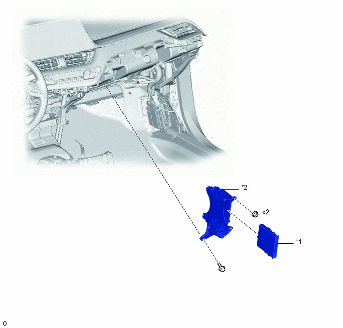
COMPONENTS
ILLUSTRATION
|
*1 |
CERTIFICATION ECU (SMART KEY ECU ASSEMBLY) |
*2 |
ECU INTEGRATION BOX RH |
Removal
REMOVAL
CAUTION / NOTICE / HINT
The necessary procedures (adjustment, calibration, initialization, or registration) that must be performed after parts are removed, installed, or replaced during the certification ECU (smart key ECU assembly) removal/installation are shown below.
Necessary Procedure After Parts Removed/Installed/Replaced|
Replacement Part or Procedure |
Necessary Procedures |
Effects / Inoperative when not performed |
Link |
|---|---|---|---|
|
Certification ECU (smart key ECU assembly) |
Perform code registration (Immobiliser system) |
|
w/ Smart Key System: |
PROCEDURE
1. REMOVE NO. 2 INSTRUMENT PANEL LOWER FINISH PANEL
Click here .gif)
2. REMOVE ECU INTEGRATION BOX RH
|
(a) Disconnect the 4 connectors. |
|
.png)
(b) Using a clip remover, disengage the wire harness clamp.
|
(c) Remove the bolt, 2 nuts and ECU integration box RH. |
|
.png)
3. REMOVE CERTIFICATION ECU (SMART KEY ECU ASSEMBLY)
(a) Using a screwdriver with its tip wrapped in protective tape, disengage the claws to remove the certification ECU (smart key ECU assembly) as shown in the illustration.
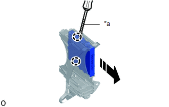
|
*a |
Protective Tape |
.png) |
Remove in this Direction |
Installation
INSTALLATION
CAUTION / NOTICE / HINT
NOTICE:
Before replacing the certification ECU (smart key ECU assembly), refer to Registration.
Click here .gif)
PROCEDURE
1. INSTALL CERTIFICATION ECU (SMART KEY ECU ASSEMBLY)
(a) Engage the claws to install the certification ECU (smart key ECU assembly) as shown in the illustration.
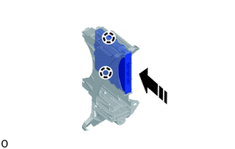
.png) |
Install in this Direction |
2. INSTALL ECU INTEGRATION BOX RH
(a) Install the ECU integration box RH with the 2 nuts and bolt.
|
(b) Engage the wire harness clamp. |
|
.png)
(c) Connect the 4 connectors.
3. INSTALL NO. 2 INSTRUMENT PANEL LOWER FINISH PANEL
Click here

 Electrical Key Oscillator(for Front Floor)
Components
COMPONENTS
ILLUSTRATION
*1
NO. 1 INDOOR ELECTRICAL KEY ANTENNA ASSEMBLY
-
-
Installation
INSTALLATION
PROCEDURE
1. INSTALL ...
Other materials:
Toyota CH-R Service Manual > Rear Console Box: Removal
REMOVAL
PROCEDURE
1. REMOVE FRONT DOOR SCUFF PLATE LH
(a) Disengage the claws and guides to remove the front door scuff plate LH as
shown in the illustration.
Place Hands Here
Remove in this Direction
2. REMOVE COWL SIDE TRIM BOARD LH
...
Toyota CH-R Service Manual > Power Mirror Control System: Parts Location
PARTS LOCATION
ILLUSTRATION
*A
w/ Retract Mirror
-
-
*1
OUTER MIRROR SWITCH ASSEMBLY
*2
OUTER REAR VIEW MIRROR ASSEMBLY LH
*3
OUTER REAR VIEW MIRROR ASSEMBLY RH
*4 ...
Toyota C-HR (AX20) 2023-2026 Owner's Manual
Toyota CH-R Owners Manual
- For safety and security
- Instrument cluster
- Operation of each component
- Driving
- Interior features
- Maintenance and care
- When trouble arises
- Vehicle specifications
- For owners
Toyota CH-R Service Manual
- Introduction
- Maintenance
- Audio / Video
- Cellular Communication
- Navigation / Multi Info Display
- Park Assist / Monitoring
- Brake (front)
- Brake (rear)
- Brake Control / Dynamic Control Systems
- Brake System (other)
- Parking Brake
- Axle And Differential
- Drive Shaft / Propeller Shaft
- K114 Cvt
- 3zr-fae Battery / Charging
- Networking
- Power Distribution
- Power Assist Systems
- Steering Column
- Steering Gear / Linkage
- Alignment / Handling Diagnosis
- Front Suspension
- Rear Suspension
- Tire / Wheel
- Tire Pressure Monitoring
- Door / Hatch
- Exterior Panels / Trim
- Horn
- Lighting (ext)
- Mirror (ext)
- Window / Glass
- Wiper / Washer
- Door Lock
- Heating / Air Conditioning
- Interior Panels / Trim
- Lighting (int)
- Meter / Gauge / Display
- Mirror (int)
- Power Outlets (int)
- Pre-collision
- Seat
- Seat Belt
- Supplemental Restraint Systems
- Theft Deterrent / Keyless Entry

0.0073