Toyota CH-R Service Manual: Removal
REMOVAL
CAUTION / NOTICE / HINT
The necessary procedures (adjustment, calibration, initialization, or registration) that must be performed after parts are removed, installed, or replaced during the lower No. 1 instrument panel airbag assembly removal/installation are shown below.
Necessary Procedure After Parts Removed/Installed/Replaced|
Replacement Part or Procedure |
Necessary Procedures |
Effects / Inoperative when not performed |
Link |
|---|---|---|---|
|
Disconnect cable from negative battery terminal |
Initialize back door lock |
Power door lock control system |
|
|
Memorize steering angle neutral point |
Lane departure alert system (w/ Steering Control) |
|
|
|
Pre-collision system |
PROCEDURE
1. PRECAUTION
CAUTION:
Be sure to read Precaution thoroughly before servicing.
Click here .gif)
.png)
NOTICE:
After turning the ignition switch off, waiting time may be required before disconnecting the cable from the negative (-) battery terminal. Therefore, make sure to read the disconnecting the cable from the negative (-) battery terminal notices before proceeding with work.
Click here
2. DISCONNECT CABLE FROM NEGATIVE BATTERY TERMINAL
Click here
CAUTION:
- Wait at least 90 seconds after disconnecting the cable from the negative
(-) battery terminal to disable the SRS system.
.png)
- If an SRS part is accidentally deployed, it may cause a serious injury.
NOTICE:
When disconnecting the cable, some systems need to be initialized after the cable is reconnected.
Click here
3. REMOVE FUSE BOX OPENING COVER
Click here
4. REMOVE INSTRUMENT CLUSTER FINISH PANEL GARNISH ASSEMBLY
Click here
5. REMOVE INSTRUMENT PANEL LOWER CENTER FINISH PANEL
Click here
6. REMOVE LOWER NO. 1 INSTRUMENT PANEL AIRBAG ASSEMBLY WITH DOOR
CAUTION:
When storing the lower No. 1 instrument panel airbag assembly with door, keep the airbag deployment side facing upward.
.png) |
Deployment Side |
(a) Check that the ignition switch off.
(b) Check that the cable is disconnected from the negative (-) battery terminal.
CAUTION:
Wait at least 90 seconds after disconnecting the cable from the negative (-) battery terminal to disable the SRS system.
|
(c) Remove the 2 bolts. |
|
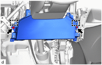
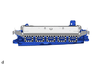
(d) Disengage the hooks to separate the lower No. 1 instrument panel airbag assembly with door.
NOTICE:
When separating the lower No. 1 instrument panel airbag assembly with door, do not pull the airbag wire harness.
|
(e) Using a screwdriver with its tip wrapped in protective tape, release the airbag connector lock. |
|
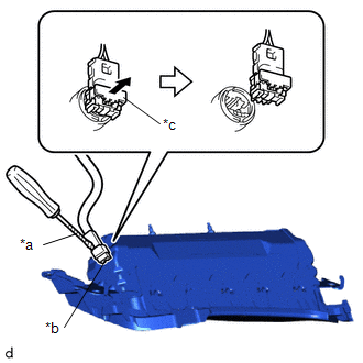
(f) Disconnect the airbag connector to remove the lower No. 1 instrument panel airbag assembly with door.
NOTICE:
When disconnecting any airbag connector, take care not to damage the airbag wire harness.
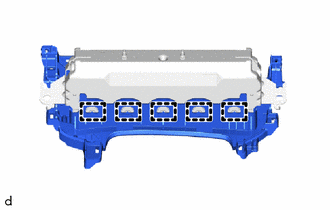
7. REMOVE LOWER NO. 1 INSTRUMENT PANEL AIRBAG DOOR (for TMMT Made)
|
(a) Disengage the hooks. |
|
|
(b) Disengage the hooks to remove the lower No. 1 instrument panel airbag door from the lower No. 1 instrument panel airbag assembly. |
|
 On-vehicle Inspection
ON-VEHICLE INSPECTION
CAUTION / NOTICE / HINT
CAUTION:
Be sure to correctly follow the removal and installation procedures for the lower
No. 1 instrument panel airbag assembly.
PROCEDURE
1. INS ...
 Disposal
DISPOSAL
CAUTION / NOTICE / HINT
CAUTION:
Before performing pre-disposal deployment of any SRS part, review and closely
follow all applicable environmental and hazardous material regulations. Pre ...
Other materials:
Toyota CH-R Service Manual > Power Steering System: Parts Location
PARTS LOCATION
ILLUSTRATION
*A
w/ Toyota Safety Sense P
-
-
*1
ECM
*2
POWER STEERING ECU ASSEMBLY
- POWER STEERING MOTOR
*3
BRAKE ACTUATOR ASSEMBLY
- SKID CONTROL ECU
...
Toyota CH-R Service Manual > Navigation System: Screen Flicker or Color Distortion
PROCEDURE
1.
CHECK DISPLAY SETTING
(a) Reset display settings (contrast, brightness) and check that the screen appears
normal.
OK:
The display returns to normal.
OK
END
NG
PROCEED TO NEXT SUSPECTED AREA SHOWN IN ...
Toyota C-HR (AX20) 2023-2026 Owner's Manual
Toyota CH-R Owners Manual
- For safety and security
- Instrument cluster
- Operation of each component
- Driving
- Interior features
- Maintenance and care
- When trouble arises
- Vehicle specifications
- For owners
Toyota CH-R Service Manual
- Introduction
- Maintenance
- Audio / Video
- Cellular Communication
- Navigation / Multi Info Display
- Park Assist / Monitoring
- Brake (front)
- Brake (rear)
- Brake Control / Dynamic Control Systems
- Brake System (other)
- Parking Brake
- Axle And Differential
- Drive Shaft / Propeller Shaft
- K114 Cvt
- 3zr-fae Battery / Charging
- Networking
- Power Distribution
- Power Assist Systems
- Steering Column
- Steering Gear / Linkage
- Alignment / Handling Diagnosis
- Front Suspension
- Rear Suspension
- Tire / Wheel
- Tire Pressure Monitoring
- Door / Hatch
- Exterior Panels / Trim
- Horn
- Lighting (ext)
- Mirror (ext)
- Window / Glass
- Wiper / Washer
- Door Lock
- Heating / Air Conditioning
- Interior Panels / Trim
- Lighting (int)
- Meter / Gauge / Display
- Mirror (int)
- Power Outlets (int)
- Pre-collision
- Seat
- Seat Belt
- Supplemental Restraint Systems
- Theft Deterrent / Keyless Entry

0.0077