Toyota CH-R Service Manual: Seat Belt Buckle Switch LH Circuit Malfunction (B1656/38)
DESCRIPTION
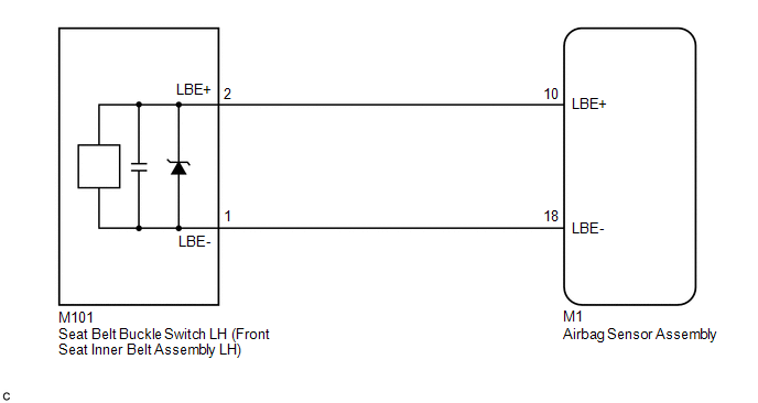
The seat belt buckle switch LH circuit consists of the airbag sensor assembly and seat belt buckle switch LH (front seat inner belt assembly LH).
DTC B1656/38 is stored when a malfunction is detected in the seat belt buckle switch LH circuit.
|
DTC No. |
Detection Item |
DTC Detection Condition |
Trouble Area |
Test Mode / Check Mode |
|---|---|---|---|---|
|
B1656/38 |
Seat Belt Buckle Switch LH Circuit Malfunction |
|
|
Does not apply to test/check mode |
WIRING DIAGRAM
CAUTION / NOTICE / HINT
NOTICE:
After turning the ignition switch off, waiting time may be required before disconnecting the cable from the negative (-) battery terminal. Therefore, make sure to read the disconnecting the cable from the negative (-) battery terminal notices before proceeding with work.
Click here .gif)
PROCEDURE
|
1. |
CHECK CONNECTORS |
(a) Turn the ignition switch off.
(b) Disconnect the cable from the negative (-) battery terminal.
CAUTION:
Wait at least 90 seconds after disconnecting the cable from the negative (-) battery terminal to disable the SRS system.
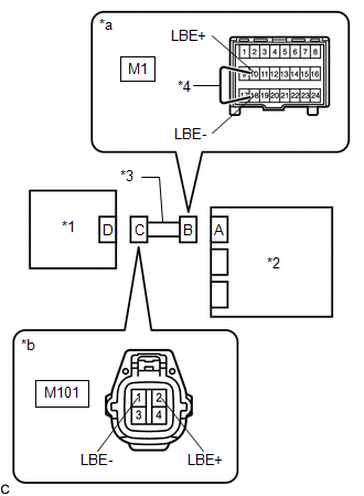
(c) Check that the connectors are properly connected to the airbag sensor assembly and front seat inner belt assembly LH.
OK:
The connectors are properly connected.
HINT:
If the connectors are not properly connected, reconnect the connectors and proceed to the next inspection.
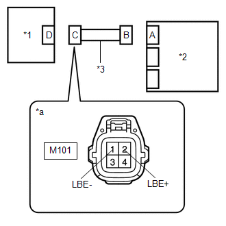
(d) Disconnect the connectors from the airbag sensor assembly and front seat inner belt assembly LH.
(e) Check that the terminals of the connectors are not deformed or damaged.
OK:
The terminals are not deformed or damaged.
| NG | .gif) |
REPLACE FLOOR WIRE |
|
.gif)
|
2. |
CHECK FLOOR WIRE (OPEN) |
|
(a) Using a service wire, connect terminals 10 (LBE+) and 18 (LBE-) of connector B. NOTICE: Do not forcibly insert the service wire into the terminals of the connector when connecting the wire. |
|
(b) Measure the resistance according to the value(s) in the table below.
Standard Resistance:
|
Tester Connection |
Condition |
Specified Condition |
|---|---|---|
|
M101-2 (LBE+) - M101-1 (LBE-) |
Always |
Below 1 Ω |
(c) Disconnect the service wire from connector B.
| NG | |
REPLACE FLOOR WIRE |
|
|
3. |
CHECK FLOOR WIRE (SHORT) |
|
(a) Measure the resistance according to the value(s) in the table below. Standard Resistance:
|
|
| NG | |
REPLACE FLOOR WIRE |
|
|
4. |
CHECK FLOOR WIRE (SHORT TO B+) |
|
(a) Connect the cable to the negative (-) battery terminal. |
|
(b) Turn the ignition switch on (IG).
(c) Measure the voltage according to the value(s) in the table below.
Standard Voltage:
|
Tester Connection |
Condition |
Specified Condition |
|---|---|---|
|
M101-2 (LBE+) - Body ground |
Ignition switch on (IG) |
Below 1 V |
|
M101-1 (LBE-) - Body ground |
Ignition switch on (IG) |
Below 1 V |
(d) Turn the ignition switch off.
(e) Disconnect the cable from the negative (-) battery terminal.
CAUTION:
Wait at least 90 seconds after disconnecting the cable from the negative (-) battery terminal to disable the SRS system.
| NG | |
REPLACE FLOOR WIRE |
|
|
5. |
CHECK FLOOR WIRE (SHORT TO GROUND) |
|
(a) Measure the resistance according to the value(s) in the table below. Standard Resistance:
|
|
| NG | |
REPLACE FLOOR WIRE |
|
|
6. |
CHECK DTC |
|
(a) Connect the connectors to the airbag sensor assembly and front seat inner belt assembly LH. |
|
(b) Connect the cable to the negative (-) battery terminal.
(c) Clear the DTCs stored in memory.
Click here
(d) Turn the ignition switch off.
(e) Turn the ignition switch on (IG), and wait for at least 60 seconds.
(f) Check for DTCs.
Click here
OK:
DTC B1656/38 is not output.
HINT:
Codes other than DTC B1656/38 may be output at this time, but they are not related to this check.
| OK | |
USE SIMULATION METHOD TO CHECK |
|
|
7. |
CHECK FRONT SEAT INNER BELT ASSEMBLY LH |
|
(a) Turn the ignition switch off. |
|
(b) Disconnect the cable from the negative (-) battery terminal.
CAUTION:
Wait at least 90 seconds after disconnecting the cable from the negative (-) battery terminal to disable the SRS system.
(c) Replace the front seat inner belt assembly LH with a known good one.
Click here
HINT:
Perform the following inspection using known good parts from another vehicle if possible.
(d) Connect the cable to the negative (-) battery terminal.
(e) Clear the DTCs stored in memory.
Click here
(f) Turn the ignition switch off.
(g) Turn the ignition switch on (IG), and wait for at least 60 seconds.
(h) Check for DTCs.
Click here
OK:
DTC B1656/38 is not output.
HINT:
Codes other than DTC B1656/38 may be output at this time, but they are not related to this check.
(i) Turn the ignition switch off.
(j) Disconnect the cable from the negative (-) battery terminal.
CAUTION:
Wait at least 90 seconds after disconnecting the cable from the negative (-) battery terminal to disable the SRS system.
(k) Restore the front seat inner belt assembly LH that was installed for testing to its original location.
Click here
| OK | |
REPLACE FRONT SEAT INNER BELT ASSEMBLY LH
|
| NG | |
REPLACE AIRBAG SENSOR ASSEMBLY |
 Pressure Sensor Difference for Front Door (B166A/72)
DESCRIPTION
The door side airbag sensor LH and door side airbag sensor RH detect impacts
to the vehicle through changes in pressure inside the front doors caused by deformation
of the outer side ...
 Front Door Pressure Sensor RH (B166C/4A,B166F/4A)
DESCRIPTION
The side collision sensor RH circuit (bus 1) consists of the airbag sensor assembly,
door side airbag sensor RH, No. 1 side airbag sensor RH and No. 2 side airbag sensor
RH.
The door ...
Other materials:
Toyota CH-R Service Manual > Parking Brake: Parking Brake System
Precaution
PRECAUTION
IGNITION SWITCH EXPRESSIONS
(a) The type of ignition switch used on this model differs depending on the specifications
of the vehicle. The expressions listed in the table below are used in this section.
Expression
Ignition Switch (Position)
...
Toyota CH-R Service Manual > Safety Connect System: Dcm Activation
DCM ACTIVATION
DCM ACTIVATION
This function should be used to activate the DCM (Telematics Transceiver) after
a new DCM (Telematics Transceiver) has been installed. During the DCM Activation
process, the Techstream automatically provides the telematics service provider with
the new DCM (Tele ...
Toyota C-HR (AX20) 2023-2026 Owner's Manual
Toyota CH-R Owners Manual
- For safety and security
- Instrument cluster
- Operation of each component
- Driving
- Interior features
- Maintenance and care
- When trouble arises
- Vehicle specifications
- For owners
Toyota CH-R Service Manual
- Introduction
- Maintenance
- Audio / Video
- Cellular Communication
- Navigation / Multi Info Display
- Park Assist / Monitoring
- Brake (front)
- Brake (rear)
- Brake Control / Dynamic Control Systems
- Brake System (other)
- Parking Brake
- Axle And Differential
- Drive Shaft / Propeller Shaft
- K114 Cvt
- 3zr-fae Battery / Charging
- Networking
- Power Distribution
- Power Assist Systems
- Steering Column
- Steering Gear / Linkage
- Alignment / Handling Diagnosis
- Front Suspension
- Rear Suspension
- Tire / Wheel
- Tire Pressure Monitoring
- Door / Hatch
- Exterior Panels / Trim
- Horn
- Lighting (ext)
- Mirror (ext)
- Window / Glass
- Wiper / Washer
- Door Lock
- Heating / Air Conditioning
- Interior Panels / Trim
- Lighting (int)
- Meter / Gauge / Display
- Mirror (int)
- Power Outlets (int)
- Pre-collision
- Seat
- Seat Belt
- Supplemental Restraint Systems
- Theft Deterrent / Keyless Entry

0.0082