Toyota CH-R Service Manual: Parts Location
PARTS LOCATION
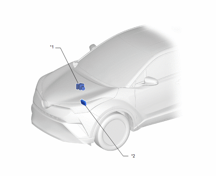
ILLUSTRATION
|
*1 |
BRAKE ACTUATOR ASSEMBLY (SKID CONTROL ECU) |
*2 |
ECM |
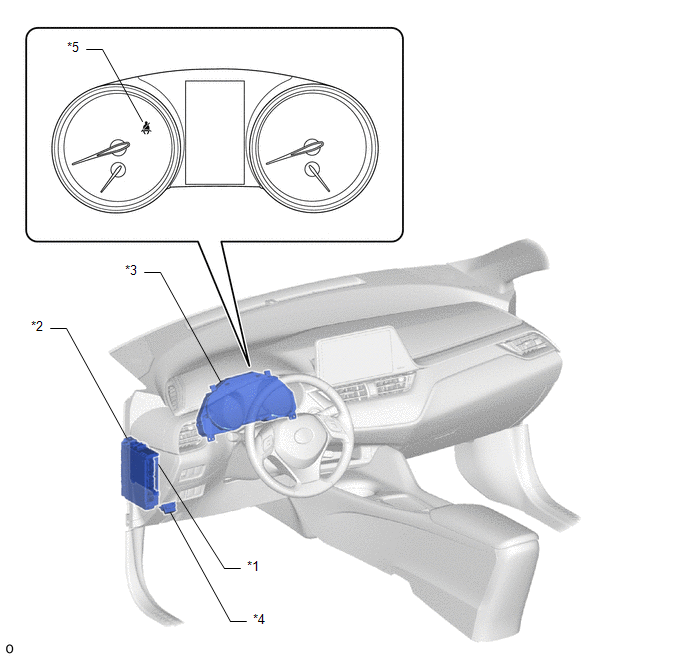
ILLUSTRATION
|
*1 |
MAIN BODY ECU (MULTIPLEX NETWORK BODY ECU) |
*2 |
INSTRUMENT PANEL JUNCTION BLOCK ASSEMBLY - ECU-DCC NO. 2 FUSE - METER-IG2 FUSE |
|
*3 |
COMBINATION METER ASSEMBLY - SEAT BELT WARNING BUZZER |
*4 |
DLC3 |
|
*5 |
SEAT BELT WARNING LIGHT |
- |
- |
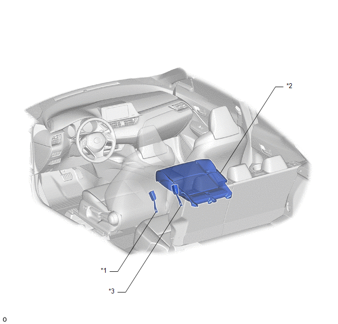
ILLUSTRATION
|
*1 |
FRONT SEAT INNER BELT ASSEMBLY (DRIVER SEAT) |
*2 |
OCCUPANT DETECTION SENSOR (SEPARATE TYPE FRONT SEAT CUSHION PAD) |
|
*3 |
FRONT SEAT INNER BELT ASSEMBLY (FRONT PASSENGER SEAT) |
- |
- |

 Precaution
PRECAUTION
IGNITION SWITCH EXPRESSIONS
HINT:
The type of ignition switch used on this model differs according to the specifications
of the vehicle. The expressions listed in the table below are u ...
Other materials:
Toyota CH-R Service Manual > Clock System: Problem Symptoms Table
PROBLEM SYMPTOMS TABLE
HINT:
Use the table below to help determine the cause of problem symptoms.
If multiple suspected areas are listed, the potential causes of the symptoms
are listed in order of probability in the "Suspected Area" column of the
table. Check each sy ...
Toyota CH-R Service Manual > Lumbar Switch: Installation
INSTALLATION
CAUTION / NOTICE / HINT
CAUTION:
Be sure to read Precaution thoroughly before servicing.
Click here
Wear protective gloves. Sharp areas on the parts may injure your hands.
HINT:
Front lumbar power seat switch is available only on the driver side ...
Toyota C-HR (AX20) 2023-2026 Owner's Manual
Toyota CH-R Owners Manual
- For safety and security
- Instrument cluster
- Operation of each component
- Driving
- Interior features
- Maintenance and care
- When trouble arises
- Vehicle specifications
- For owners
Toyota CH-R Service Manual
- Introduction
- Maintenance
- Audio / Video
- Cellular Communication
- Navigation / Multi Info Display
- Park Assist / Monitoring
- Brake (front)
- Brake (rear)
- Brake Control / Dynamic Control Systems
- Brake System (other)
- Parking Brake
- Axle And Differential
- Drive Shaft / Propeller Shaft
- K114 Cvt
- 3zr-fae Battery / Charging
- Networking
- Power Distribution
- Power Assist Systems
- Steering Column
- Steering Gear / Linkage
- Alignment / Handling Diagnosis
- Front Suspension
- Rear Suspension
- Tire / Wheel
- Tire Pressure Monitoring
- Door / Hatch
- Exterior Panels / Trim
- Horn
- Lighting (ext)
- Mirror (ext)
- Window / Glass
- Wiper / Washer
- Door Lock
- Heating / Air Conditioning
- Interior Panels / Trim
- Lighting (int)
- Meter / Gauge / Display
- Mirror (int)
- Power Outlets (int)
- Pre-collision
- Seat
- Seat Belt
- Supplemental Restraint Systems
- Theft Deterrent / Keyless Entry

0.0073