Toyota CH-R Service Manual: Parts Location
PARTS LOCATION
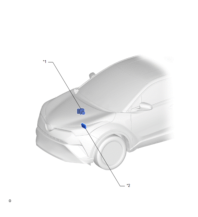
ILLUSTRATION
|
*1 |
BRAKE ACTUATOR ASSEMBLY (SKID CONTROL ECU) |
*2 |
ECM |
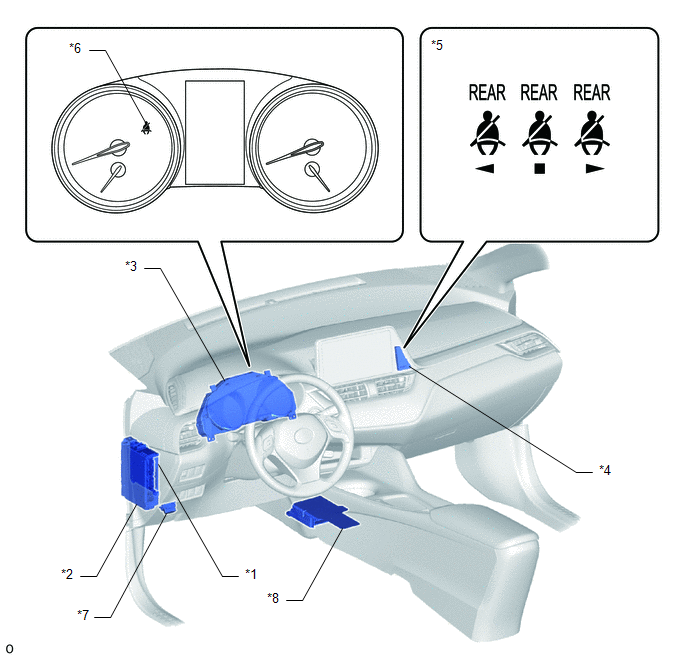
ILLUSTRATION
|
*1 |
MAIN BODY ECU (MULTIPLEX NETWORK BODY ECU) |
*2 |
INSTRUMENT PANEL JUNCTION BLOCK ASSEMBLY - ECU-DCC NO. 1 FUSE - ECU-IG1 NO. 4 FUSE |
|
*3 |
COMBINATION METER ASSEMBLY - SEAT BELT WARNING BUZZER |
*4 |
CLOCK ASSEMBLY |
|
*5 |
REAR SEAT BELT WARNING LIGHT |
*6 |
SEAT BELT WARNING LIGHT |
|
*7 |
DLC3 |
*8 |
AIRBAG SENSOR ASSEMBLY |
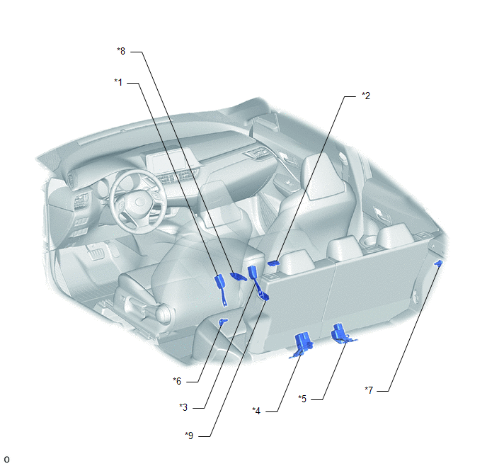
ILLUSTRATION
|
*1 |
FRONT SEAT INNER BELT ASSEMBLY (DRIVER SEAT) |
*2 |
OCCUPANT DETECTION ECU |
|
*3 |
FRONT SEAT INNER BELT ASSEMBLY (FRONT PASSENGER SEAT) |
*4 |
REAR SEAT INNER WITH CENTER BELT ASSEMBLY LH |
|
*5 |
REAR SEAT INNER BELT ASSEMBLY RH |
*6 |
REAR DOOR COURTESY LIGHT SWITCH ASSEMBLY (for LH) |
|
*7 |
REAR DOOR COURTESY LIGHT SWITCH ASSEMBLY (for RH) |
*8 |
FRONT OCCUPANT CLASSIFICATION SENSOR LH |
|
*9 |
REAR OCCUPANT CLASSIFICATION SENSOR LH |
- |
- |

 Precaution
PRECAUTION
IGNITION SWITCH EXPRESSIONS
HINT:
The type of ignition switch used on this model differs depending on the specifications
of the vehicle. The expressions listed in the table below are u ...
Other materials:
Toyota CH-R Service Manual > Airbag System: Short in Front Pretensioner Squib RH Circuit (B1900/73-B1903/73)
DESCRIPTION
The front pretensioner squib RH circuit consists of the airbag sensor assembly
and front seat outer belt assembly RH.
The airbag sensor assembly uses this circuit to deploy the pretensioner when
deployment conditions are met.
These DTCs are stored when a malfunction is detected in ...
Toyota CH-R Service Manual > Center Airbag Sensor Assembly: Removal
REMOVAL
CAUTION / NOTICE / HINT
The necessary procedures (adjustment, calibration, initialization, or registration)
that must be performed after parts are removed, installed, or replaced during the
airbag sensor assembly removal/installation are shown below.
Necessary Procedure After Parts Re ...
Toyota C-HR (AX20) 2023-2026 Owner's Manual
Toyota CH-R Owners Manual
- For safety and security
- Instrument cluster
- Operation of each component
- Driving
- Interior features
- Maintenance and care
- When trouble arises
- Vehicle specifications
- For owners
Toyota CH-R Service Manual
- Introduction
- Maintenance
- Audio / Video
- Cellular Communication
- Navigation / Multi Info Display
- Park Assist / Monitoring
- Brake (front)
- Brake (rear)
- Brake Control / Dynamic Control Systems
- Brake System (other)
- Parking Brake
- Axle And Differential
- Drive Shaft / Propeller Shaft
- K114 Cvt
- 3zr-fae Battery / Charging
- Networking
- Power Distribution
- Power Assist Systems
- Steering Column
- Steering Gear / Linkage
- Alignment / Handling Diagnosis
- Front Suspension
- Rear Suspension
- Tire / Wheel
- Tire Pressure Monitoring
- Door / Hatch
- Exterior Panels / Trim
- Horn
- Lighting (ext)
- Mirror (ext)
- Window / Glass
- Wiper / Washer
- Door Lock
- Heating / Air Conditioning
- Interior Panels / Trim
- Lighting (int)
- Meter / Gauge / Display
- Mirror (int)
- Power Outlets (int)
- Pre-collision
- Seat
- Seat Belt
- Supplemental Restraint Systems
- Theft Deterrent / Keyless Entry

0.0085