Toyota CH-R Service Manual: Installation
INSTALLATION
CAUTION / NOTICE / HINT
HINT:
- Use the same procedure for the RH side and LH side.
- The procedure listed below is for the LH side.
PROCEDURE
1. INSTALL FRONT SHOULDER BELT ANCHOR ADJUSTER ASSEMBLY
|
(a) Engage the guide and temporarily install the front shoulder belt anchor adjuster assembly with the 2 bolts. |
|
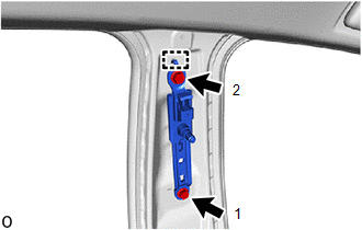
(b) Tighten the 2 bolts in the order shown in the illustration.
Torque:
42 N·m {428 kgf·cm, 31 ft·lbf}
2. INSPECT FRONT SEAT OUTER BELT ASSEMBLY
Click here .gif)
3. INSTALL FRONT SEAT OUTER BELT ASSEMBLY
|
(a) Engage the guides to install the front seat outer belt assembly. |
|
.png)
(b) Install the bolt.
Torque:
12.5 N·m {127 kgf·cm, 9 ft·lbf}
|
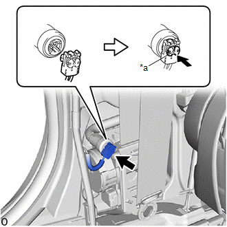
(c) Connect the pretensioner connector and lock the locking button as shown in the illustration. NOTICE: Securely lock the locking button. |
|
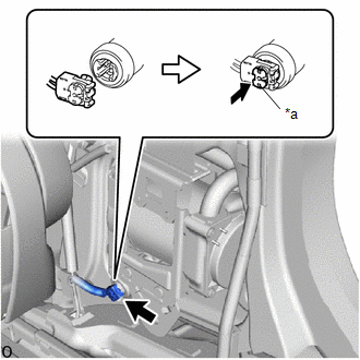
(d) for Front Passenger Seat Belt with Selectable Force Limiter:
|
(1) Connect the selectable force limiter connector and lock the locking button as shown in the illustration. NOTICE: Securely lock the locking button. |
|
(e) Connect the shoulder anchor of the front seat outer belt assembly with the nut.
Torque:
42 N·m {428 kgf·cm, 31 ft·lbf}
(f) Install the bolt of retractor lower side.
Torque:
42 N·m {428 kgf·cm, 31 ft·lbf}
(g) Check that the ELR locks.
NOTICE:
This check should be performed with the front seat outer belt assembly installed to the vehicle.
(1) With the front seat outer belt assembly installed to the vehicle, check that the belt locks when it is pulled out quickly.
(h) Remove the bolt of retractor lower side.
4. INSTALL CENTER PILLAR GARNISH ASSEMBLY
Click here
5. INSTALL CENTER PILLAR LOWER GARNISH
Click here
6. CONNECT FRONT SEAT OUTER BELT ASSEMBLY
(a) Connect the floor anchor of the front seat outer belt assembly with the bolt.
Torque:
42 N·m {428 kgf·cm, 31 ft·lbf}
7. INSTALL LAP BELT OUTER ANCHOR COVER
(a) Engage the guide and claws to install the lap belt outer anchor cover.
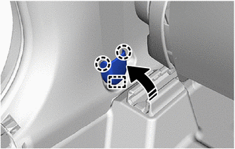
.png) |
Install in this Direction |
8. CONNECT REAR DOOR OPENING TRIM WEATHERSTRIP
(a) Connect the rear door opening trim weatherstrip.
9. INSTALL REAR DOOR SCUFF PLATE (w/o Rear Seat Side Airbag)
Click here
10. INSTALL REAR DOOR SCUFF PLATE (w/ Rear Seat Side Airbag)
Click here
11. CONNECT FRONT DOOR OPENING TRIM WEATHERSTRIP
(a) Connect the front door opening trim weatherstrip.
12. INSTALL FRONT DOOR SCUFF PLATE
Click here
13. INSTALL BENCH TYPE REAR SEAT CUSHION ASSEMBLY
Click here
14. CONNECT CABLE TO NEGATIVE BATTERY TERMINAL
Click here
NOTICE:
When disconnecting the cable, some systems need to be initialized after the cable is reconnected.
Click here
15. PERFORM DIAGNOSTIC SYSTEM CHECK
Click here
16. INSPECT SRS WARNING LIGHT
Click here
 Inspection
INSPECTION
PROCEDURE
1. INSPECT FRONT SEAT OUTER BELT ASSEMBLY
*a
Retractor
*b
Unlock
*c
Lock
*d
...
 Disposal
DISPOSAL
CAUTION / NOTICE / HINT
CAUTION:
Before performing pre-disposal deployment of any SRS part, review and closely
follow all applicable environmental and hazardous material regulations. Pre ...
Other materials:
Toyota CH-R Service Manual > Air Conditioning System(for Automatic Air Conditioning System With Top-mounted
Air Conditioner Pressure Sensor): Diagnostic Trouble Code Chart
DIAGNOSTIC TROUBLE CODE CHART
AIR CONDITIONING SYSTEM
DTC No.
Detection Item
DTC Detection Condition
Link
B1411
Room Temperature Sensor Circuit
Any of the following conditions is met:
Open in cooler th ...
Toyota CH-R Service Manual > Windshield Outside Moulding: Components
COMPONENTS
ILLUSTRATION
*1
NO. 1 WINDSHIELD OUTSIDE MOULDING CLIP
*2
NO. 3 WINDSHIELD OUTSIDE MOULDING CLIP
*3
WINDSHIELD OUTSIDE MOULDING
*4
WINDSHIELD GLASS SUB-ASSEMBLY
●
...
Toyota C-HR (AX20) 2023-2026 Owner's Manual
Toyota CH-R Owners Manual
- For safety and security
- Instrument cluster
- Operation of each component
- Driving
- Interior features
- Maintenance and care
- When trouble arises
- Vehicle specifications
- For owners
Toyota CH-R Service Manual
- Introduction
- Maintenance
- Audio / Video
- Cellular Communication
- Navigation / Multi Info Display
- Park Assist / Monitoring
- Brake (front)
- Brake (rear)
- Brake Control / Dynamic Control Systems
- Brake System (other)
- Parking Brake
- Axle And Differential
- Drive Shaft / Propeller Shaft
- K114 Cvt
- 3zr-fae Battery / Charging
- Networking
- Power Distribution
- Power Assist Systems
- Steering Column
- Steering Gear / Linkage
- Alignment / Handling Diagnosis
- Front Suspension
- Rear Suspension
- Tire / Wheel
- Tire Pressure Monitoring
- Door / Hatch
- Exterior Panels / Trim
- Horn
- Lighting (ext)
- Mirror (ext)
- Window / Glass
- Wiper / Washer
- Door Lock
- Heating / Air Conditioning
- Interior Panels / Trim
- Lighting (int)
- Meter / Gauge / Display
- Mirror (int)
- Power Outlets (int)
- Pre-collision
- Seat
- Seat Belt
- Supplemental Restraint Systems
- Theft Deterrent / Keyless Entry

0.0107