Toyota CH-R Service Manual: Installation
INSTALLATION
CAUTION / NOTICE / HINT
HINT:
- Use the same procedure for the driver side and front passenger side.
- The procedure listed below is for the driver side.
PROCEDURE
1. INSTALL FRONT SEAT INNER BELT ASSEMBLY (for Driver Side)
(a) Install the front seat belt anchor plate.
|
(b) Install the front seat inner belt assembly with the nut. Torque: 42 N·m {428 kgf·cm, 31 ft·lbf} NOTICE: Do not allow the anchor part of the front seat inner belt assembly to overlap the protruding part of the front seat adjuster assembly. |
|
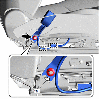
(c) Engage the clamps.
(d) w/o Occupant Classification System:
|
(1) Engage the claw and clamp. |
|
.png)
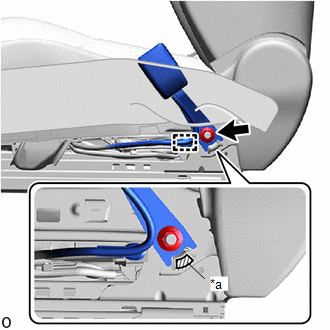
(e) w/ Occupant Classification System:
|
(1) Engage the claw and clamp. |
|
.png)
(2) Connect the connector.
2. INSTALL FRONT SEAT INNER BELT ASSEMBLY (for Front Passenger Side)
(a) Install the front seat belt anchor plate.
(b) w/o Occupant Classification System:
|
(1) Install the front seat inner belt assembly with the nut. Torque: 42 N·m {428 kgf·cm, 31 ft·lbf} NOTICE: Do not allow the anchor part of the front seat inner belt assembly to overlap the protruding part of the front seat adjuster assembly. |
|
(2) Engage the clamp.
|
(3) Engage the claw and clamps. |
|
.png)
(4) Connect the connector.
(c) w/ Occupant Classification System:
|
(1) Install the front seat inner belt assembly with the nut. Torque: 42 N·m {428 kgf·cm, 31 ft·lbf} NOTICE: Do not allow the anchor part of the front seat inner belt assembly to overlap the protruding part of the front seat adjuster assembly. |
|
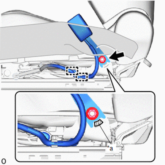
(2) Engage the clamps.
|
(3) Engage the claw and clamp. |
|
.png)
3. INSTALL FRONT SEAT ASSEMBLY
Click here .gif)
 Removal
REMOVAL
CAUTION / NOTICE / HINT
The necessary procedures (adjustment, calibration, initialization, or registration)
that must be performed after parts are removed and installed, or replaced during ...

Other materials:
Toyota CH-R Service Manual > Smart Key System(for Start Function): Steering Lock Position Signal Circuit Malfunction (B2285)
DESCRIPTION
This DTC is stored when the steering lock position signal sent by the steering
lock ECU (steering lock actuator or upper bracket assembly) via direct line and
the steering lock position signal sent via LIN communication do not match.
DTC No.
Detection Item
...
Toyota CH-R Service Manual > Lighting System: Door Unlock Detection Switch Circuit
DESCRIPTION
The main body ECU (multiplex network body ECU) detects the condition of each
door unlock detection switch.
WIRING DIAGRAM
CAUTION / NOTICE / HINT
NOTICE:
Before replacing the main body ECU (multiplex network body ECU), refer to Registration*1.
Click here
*1: w/ Smart ...
Toyota C-HR (AX20) 2023-2026 Owner's Manual
Toyota CH-R Owners Manual
- For safety and security
- Instrument cluster
- Operation of each component
- Driving
- Interior features
- Maintenance and care
- When trouble arises
- Vehicle specifications
- For owners
Toyota CH-R Service Manual
- Introduction
- Maintenance
- Audio / Video
- Cellular Communication
- Navigation / Multi Info Display
- Park Assist / Monitoring
- Brake (front)
- Brake (rear)
- Brake Control / Dynamic Control Systems
- Brake System (other)
- Parking Brake
- Axle And Differential
- Drive Shaft / Propeller Shaft
- K114 Cvt
- 3zr-fae Battery / Charging
- Networking
- Power Distribution
- Power Assist Systems
- Steering Column
- Steering Gear / Linkage
- Alignment / Handling Diagnosis
- Front Suspension
- Rear Suspension
- Tire / Wheel
- Tire Pressure Monitoring
- Door / Hatch
- Exterior Panels / Trim
- Horn
- Lighting (ext)
- Mirror (ext)
- Window / Glass
- Wiper / Washer
- Door Lock
- Heating / Air Conditioning
- Interior Panels / Trim
- Lighting (int)
- Meter / Gauge / Display
- Mirror (int)
- Power Outlets (int)
- Pre-collision
- Seat
- Seat Belt
- Supplemental Restraint Systems
- Theft Deterrent / Keyless Entry

0.0116