Toyota CH-R Service Manual: Removal
REMOVAL
CAUTION / NOTICE / HINT
The necessary procedures (adjustment, calibration, initialization, or registration) that must be performed after parts are removed, installed, or replaced during the lumbar support adjuster assembly removal/installation are shown below.
Necessary Procedure After Parts Removed/Installed/Replaced|
Replacement Part or Procedure |
Necessary Procedures |
Effects / Inoperative when not performed |
Link |
|---|---|---|---|
|
Disconnect cable from negative battery terminal |
Initialize back door lock |
Power door lock control system |
|
|
Memorize steering angle neutral point |
Lane departure alert system (w/ Steering Control) |
|
|
|
Pre-collision system |
CAUTION:
- Be sure to read Precaution thoroughly before servicing.
.gif)
.png)
- Wear protective gloves. Sharp areas on the parts may injure your hands.
HINT:
Lumbar support adjuster assembly is available only on the driver side.
PROCEDURE
1. REMOVE SEPARATE TYPE FRONT SEATBACK COVER WITH PAD
Click here
2. REMOVE LUMBAR SUPPORT ADJUSTER ASSEMBLY
|
(a) Disconnect the connector. |
|
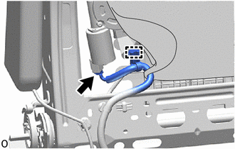
(b) Disengage the clamp.
|
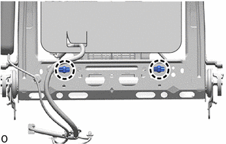
(c) Disengage the claws to separate the 2 front seatback edge protectors from the front seatback frame sub-assembly. |
|
(d) Disengage the guides to remove the lumbar support adjuster assembly from the front seatback frame sub-assembly as shown in the illustration.
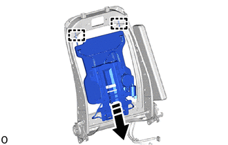
.png) |
Remove in this Direction |
|
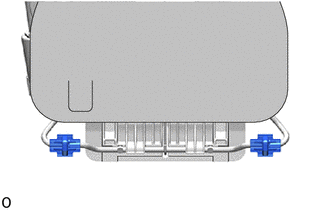
(e) Remove the 2 front seatback edge protectors from the lumbar support adjuster assembly. |
|
 Components
COMPONENTS
ILLUSTRATION
*1
LUMBAR SUPPORT ADJUSTER ASSEMBLY
*2
FRONT SEATBACK EDGE PROTECTOR
...
 Inspection
INSPECTION
PROCEDURE
1. INSPECT LUMBAR SUPPORT ADJUSTER ASSEMBLY
(a) Check the operation of the lumbar support adjuster assembly.
(1) Apply battery voltage to the lumbar motor connect ...
Other materials:
Toyota CH-R Service Manual > Power Steering System: Torque Sensor Zero Point Adjustment Undone (C1515)
DESCRIPTION
This DTC does not indicate a malfunction. The power steering ECU assembly stores
this DTC when it determines that torque sensor zero point calibration has not been
performed.
DTC No.
Detection Item
DTC Detection Condition
Trouble Area
...
Toyota CH-R Service Manual > Immobiliser System(w/ Smart Key System): Diagnostic Trouble Code Chart
DIAGNOSTIC TROUBLE CODE CHART
Immobiliser System
DTC No.
Detection Item
Link
B2779
Engine Starter Communication Malfunction
B2784
Antenna Coil Open / Short
B278A
...
Toyota C-HR (AX20) 2023-2026 Owner's Manual
Toyota CH-R Owners Manual
- For safety and security
- Instrument cluster
- Operation of each component
- Driving
- Interior features
- Maintenance and care
- When trouble arises
- Vehicle specifications
- For owners
Toyota CH-R Service Manual
- Introduction
- Maintenance
- Audio / Video
- Cellular Communication
- Navigation / Multi Info Display
- Park Assist / Monitoring
- Brake (front)
- Brake (rear)
- Brake Control / Dynamic Control Systems
- Brake System (other)
- Parking Brake
- Axle And Differential
- Drive Shaft / Propeller Shaft
- K114 Cvt
- 3zr-fae Battery / Charging
- Networking
- Power Distribution
- Power Assist Systems
- Steering Column
- Steering Gear / Linkage
- Alignment / Handling Diagnosis
- Front Suspension
- Rear Suspension
- Tire / Wheel
- Tire Pressure Monitoring
- Door / Hatch
- Exterior Panels / Trim
- Horn
- Lighting (ext)
- Mirror (ext)
- Window / Glass
- Wiper / Washer
- Door Lock
- Heating / Air Conditioning
- Interior Panels / Trim
- Lighting (int)
- Meter / Gauge / Display
- Mirror (int)
- Power Outlets (int)
- Pre-collision
- Seat
- Seat Belt
- Supplemental Restraint Systems
- Theft Deterrent / Keyless Entry

0.0078