Toyota CH-R Service Manual: Terminals Of Ecu
TERMINALS OF ECU

CHECK MILLIMETER WAVE RADAR SENSOR
(a) Measure the voltage and resistance according to the value(s) in the table below.
HINT:
If the result is not as specified, there may be a malfunction on the wire harness side.
|
Terminal No. (Symbol) |
Wiring Color |
Terminal Description |
Condition |
Specified Condition |
|---|---|---|---|---|
|
A2-8 (IGB) - A2-1 (SGND) |
B - W-B |
Power source |
Ignition switch ON |
11 to 14 V |
|
A2-1 (SGND) - Body ground |
W-B - Body ground |
Ground |
Always |
Below 1 Ω |
(b) Check for pulses according to the value(s) in the table below.
|
Terminal No. (Symbol) |
Wiring Color |
Terminal Description |
Condition |
Specified Condition |
|---|---|---|---|---|
|
A2-3 (CA2H) - A2-1 (SGND) |
G - W-B |
CAN communication signal |
Ignition switch ON |
Pulse generation (See waveform 1) |
|
A2-2 (CA2L) - A2-1 (SGND) |
GR - W-B |
CAN communication signal |
Ignition switch ON |
Pulse generation (See waveform 2) |
|
A2-5 (CA1P) - A2-1 (SGND) |
G - W-B |
CAN communication signal |
Ignition switch ON |
Pulse generation (See waveform 1) |
|
A2-6 (CA1N) - A2-1 (SGND) |
R - W-B |
CAN communication signal |
Ignition switch ON |
Pulse generation (See waveform 2) |
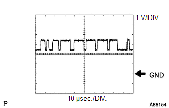
(c) WAVEFORM 1
(1) CAN communication signal
|
Item |
Content |
|---|---|
|
Terminal Name |
Between A2-3 (CA2H) and A2-1 (SGND) Between A2-5 (CA1P) and A2-1 (SGND) |
|
Tester Range |
1 V/DIV., 10 μsec./DIV. |
|
Condition |
Ignition switch ON |
HINT:
The waveform varies depending on the CAN communication signal.
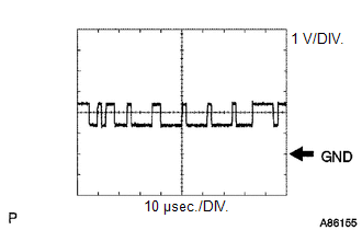
(d) WAVEFORM 2
(1) CAN communication signal
|
Item |
Content |
|---|---|
|
Terminal Name |
Between A2-2 (CA2L) and A2-1 (SGND) Between A2-6 (CA1N) and A2-1 (SGND) |
|
Tester Range |
1 V/DIV., 10 μsec./DIV. |
|
Condition |
Ignition switch ON |
HINT:
The waveform varies depending on the CAN communication signal.

CHECK FORWARD RECOGNITION CAMERA
(a) Measure the voltage and resistance according to the value(s) in the table below.
HINT:
If the result is not as specified, there may be a malfunction on the wire harness side.
|
Terminal No. (Symbol) |
Wiring Color |
Terminal Description |
Condition |
Specified Condition |
|---|---|---|---|---|
|
R5-8 (BZ) - R5-10 (GND) |
B - W-B |
Pre-collision city buzzer |
Ignition switch ON, pre-collision city buzzer not operating |
11 to 14 V |
|
Ignition switch ON, pre-collision city buzzer operating |
0 to 1.5 V |
|||
|
R5-3 (LKSW) - R5-10 (GND) |
R - W-B |
Pre-collision system cancel switch assembly |
Pre-collision system cancel switch assembly being pressed |
Below 1 Ω |
|
Pre-collision system cancel switch assembly not being pressed |
100 kΩ or higher |
|||
|
R5-7 (IGB) - R5-10 (GND) |
B - W-B |
Power source |
Ignition switch ON |
11 to 14 V |
|
Ignition switch off |
Below 1 V |
|||
|
R5-10 (GND) - Body ground |
W-B - Body ground |
Ground |
Always |
Below 1 Ω |
(b) Check for pulses according to the value(s) in the table below.
|
Terminal No. (Symbol) |
Wiring Color |
Terminal Description |
Condition |
Specified Condition |
|---|---|---|---|---|
|
R5-5 (CA1P) - R5-10 (GND) |
R - W-B |
CAN communication signal |
Ignition switch ON |
Pulse generation (See waveform 1) |
|
R5-6 (CANH) - R5-10 (GND) |
G - W-B |
CAN communication signal |
Ignition switch ON |
Pulse generation (See waveform 1) |
|
R5-11 (CA1N) - R5-10 (GND) |
GR - W-B |
CAN communication signal |
Ignition switch ON |
Pulse generation (See waveform 2) |
|
R5-12 (CANL) - R5-10 (GND) |
R - W-B |
CAN communication signal |
Ignition switch ON |
Pulse generation (See waveform 2) |
(c) WAVEFORM 1
(1) CAN communication signal
|
Item |
Content |
|---|---|
|
Terminal Name |
Between R5-5 (CA1P) - R5-10 (GND) Between R5-6 (CANH) - R5-10 (GND) |
|
Tester Range |
1 V/DIV., 10 μsec./DIV. |
|
Condition |
Ignition switch ON |
HINT:
The waveform varies depending on the CAN communication signal.
(d) WAVEFORM 2
(1) CAN communication signal
|
Item |
Content |
|---|---|
|
Terminal Name |
Between R5-11 (CA1N) - R5-10 (GND) Between R5-12 (CANL) - R5-10 (GND) |
|
Tester Range |
1 V/DIV., 10 μsec./DIV. |
|
Condition |
Ignition switch ON |
HINT:
The waveform varies depending on the CAN communication signal.
 Problem Symptoms Table
PROBLEM SYMPTOMS TABLE
HINT:
Use the table below to help determine the cause of problem symptoms.
If multiple suspected areas are listed, the potential causes of the symptoms
are lis ...
 Diagnosis System
DIAGNOSIS SYSTEM
CHECK DLC3
(a) Check the DLC3.
Click here
FUNCTION OF WARNING INDICATOR AND MESSAGE
(a) If the pre-collision system is not functioning properly, the driver is warned
by the P ...
Other materials:
Toyota CH-R Owners Manual > Adjusting the steering wheel and mirrors: Steering wheel
Adjustment procedure
1. Hold the steering wheel and push the lever down.
2. Adjust to the ideal position by moving the steering wheel horizontally and
vertically.
After adjustment, pull the lever up to secure the steering wheel.
Horn
To sound the horn, press on or close to the
mark.
...
Toyota CH-R Service Manual > Heating / Air Conditioning: Ambient Temperature Sensor
Components
COMPONENTS
ILLUSTRATION
*1
THERMISTOR ASSEMBLY
-
-
Removal
REMOVAL
PROCEDURE
1. REMOVE FRONT BUMPER ASSEMBLY
Click here
2. REMOVE THERMISTOR ASSEMBLY
(a) Disconnect the connector.
...
Toyota C-HR (AX20) 2023-2026 Owner's Manual
Toyota CH-R Owners Manual
- For safety and security
- Instrument cluster
- Operation of each component
- Driving
- Interior features
- Maintenance and care
- When trouble arises
- Vehicle specifications
- For owners
Toyota CH-R Service Manual
- Introduction
- Maintenance
- Audio / Video
- Cellular Communication
- Navigation / Multi Info Display
- Park Assist / Monitoring
- Brake (front)
- Brake (rear)
- Brake Control / Dynamic Control Systems
- Brake System (other)
- Parking Brake
- Axle And Differential
- Drive Shaft / Propeller Shaft
- K114 Cvt
- 3zr-fae Battery / Charging
- Networking
- Power Distribution
- Power Assist Systems
- Steering Column
- Steering Gear / Linkage
- Alignment / Handling Diagnosis
- Front Suspension
- Rear Suspension
- Tire / Wheel
- Tire Pressure Monitoring
- Door / Hatch
- Exterior Panels / Trim
- Horn
- Lighting (ext)
- Mirror (ext)
- Window / Glass
- Wiper / Washer
- Door Lock
- Heating / Air Conditioning
- Interior Panels / Trim
- Lighting (int)
- Meter / Gauge / Display
- Mirror (int)
- Power Outlets (int)
- Pre-collision
- Seat
- Seat Belt
- Supplemental Restraint Systems
- Theft Deterrent / Keyless Entry

0.0076