Toyota CH-R Service Manual: Terminals Of Ecu
TERMINALS OF ECU
|
*A |
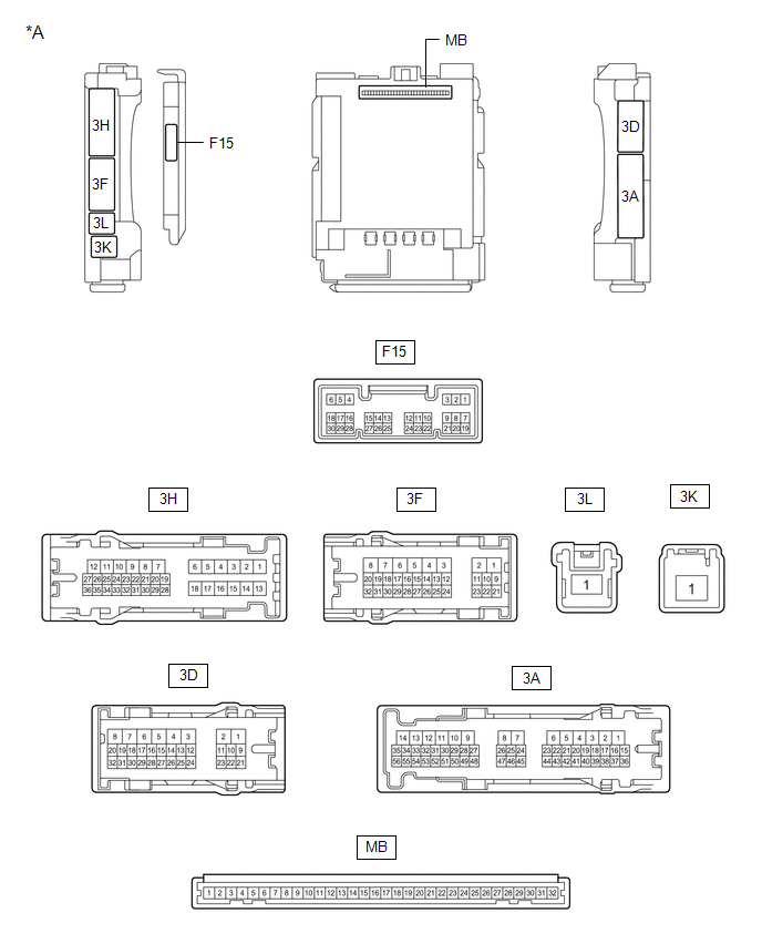
Main Body ECU (Multiplex Network Body ECU) with 1 Connector |
- |
- |
|
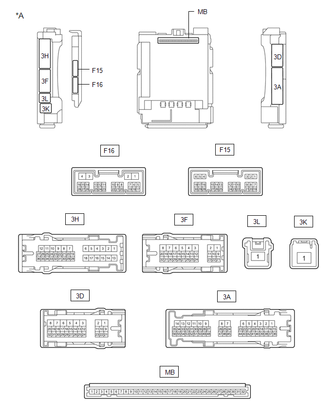
*A |
Main Body ECU (Multiplex Network Body ECU) with 2 Connectors |
- |
- |
CHECK INSTRUMENT PANEL JUNCTION BLOCK ASSEMBLY AND MAIN BODY ECU (MULTIPLEX NETWORK BODY ECU)
(a) Disconnect the instrument panel junction block assembly and main body ECU (multiplex network body ECU) connectors.
(b) Measure the voltage and resistance according to the value(s) in the table below.
|
Terminal No. (Symbol) |
Wiring Color |
Terminal Description |
Condition |
Specified Condition |
|---|---|---|---|---|
|
3F-1 - Body ground |
W - Body ground |
Battery power supply |
Always |
11 to 14 V |
|
3K-1 - Body ground |
B-R - Body ground |
Battery power supply |
Always |
11 to 14 V |
|
3D-3 - Body ground |
W-B - Body ground |
Ground |
Always |
Below 1 Ω |
If the result is not as specified, there may be a malfunction in the wire harness.
(c) Reconnect the instrument panel junction block assembly and main body ECU (multiplex network body ECU) connectors.
(d) Measure the voltage and check for pulses according to the value(s) in the table below.
|
Terminal No. (Symbol) |
Wiring Color |
Terminal Description |
Condition |
Specified Condition |
|---|---|---|---|---|
|
3A-30 - Body ground |
LG - Body ground*1 G - Body ground*2 |
ACC power supply |
Ignition switch ACC |
11 to 14 V |
|
Ignition switch off |
Below 1 V |
|||
|
3A-17 - Body ground |
GR - Body ground |
IG power supply |
Ignition switch ON |
11 to 14 V |
|
Ignition switch off |
Below 1 V |
|||
|
3D-24*3 - Body ground |
L - Body ground |
Door ambient illumination light RH power supply |
Always |
11 to 14 V |
|
3D-25*3 - Body ground |
G - Body ground |
Door ambient illumination light LH power supply |
Always |
11 to 14 V |
|
3D-26*3 - Body ground |
P - Body ground |
No. 1 cup holder illumination light power supply |
Always |
11 to 14 V |
|
3D-27*3 - Body ground |
R - Body ground |
No. 2 cup holder illumination light power supply |
Always |
11 to 14 V |
|
3H-19 - Body ground |
L - Body ground |
No. 1 luggage compartment light power supply |
DOME CUT relay on |
11 to 14 V |
|
DOME CUT relay off |
Below 1 V |
|||
|
3D-9 - Body ground |
W - Body ground |
Map light assembly, No. 1 room light and vanity lights power supply |
DOME CUT relay on |
11 to 14 V |
|
DOME CUT relay off |
Below 1 V |
|||
|
3D-29 - Body ground |
G - Body ground |
Interior lights drive output |
Interior lights off (when operated by illuminated entry system) |
11 to 14 V |
|
Interior lights on (when operated by illuminated entry system) |
Below 1 V |
|||
|
3H-24 - Body ground |
BR - Body ground |
Rear door courtesy light switch LH input |
Rear door LH open |
Below 1 V |
|
Rear door LH closed |
Pulse generation |
|||
|
3A-31 - Body ground |
BR - Body ground |
Rear door courtesy light switch RH input |
Rear door RH open |
Below 1 V |
|
Rear door RH closed |
Pulse generation |
|||
|
F15-6 (FLCY) - Body ground |
R - Body ground |
Front door courtesy light switch LH input |
Front door LH open |
Below 1 V |
|
Front door LH closed |
Pulse generation |
|||
|
F15-27 (FRCY) - Body ground |
BR - Body ground |
Front door courtesy light switch RH input |
Front door RH open |
Below 1 V |
|
Front door RH closed |
Pulse generation |
|||
|
3D-14*1 - Body ground |
LG - Body ground |
Rear door unlock detection switch input |
Rear door locked |
Pulse generation |
|
Rear door unlocked |
Below 1 V |
|||
|
3D-13 - Body ground |
B - Body ground |
Front door unlock detection switch LH input |
Front door LH locked |
Pulse generation |
|
Front door LH unlocked |
Below 1 V |
|||
|
3D-12 - Body ground |
GR - Body ground |
Front door unlock detection switch RH input |
Front door RH locked |
Pulse generation |
|
Front door RH unlocked |
Below 1 V |
|||
|
F15-25 (BCYL) - Body ground |
Y - Body ground |
No. 1 luggage compartment light drive output |
No. 1 luggage compartment light off |
11 to 14 V |
|
No. 1 luggage compartment light on |
Below 1 V |
|||
|
3H-34 - Body ground |
SB - Body ground |
Back door courtesy light switch input |
Back door open |
Below 1 V |
|
Back door closed |
11 to 14 V |
If the result is not as specified, the main body ECU (multiplex network body ECU) or instrument panel junction block assembly may be malfunctioning.
- *1: w/ Smart Key System
- *2: w/o Smart Key System
- *3: w/ Door Ambient Illumination Light
CHECK CERTIFICATION ECU (SMART KEY ECU ASSEMBLY) (w/ Smart Key System)
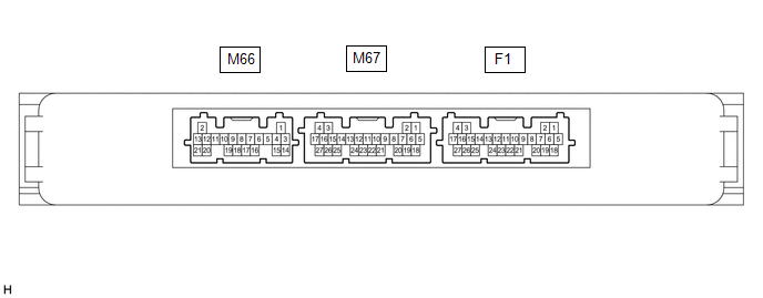
(a) Measure the voltage according to the value(s) in the table below.
|
Terminal No. (Symbol) |
Wiring Color |
Terminal Description |
Condition |
Specified Condition |
|---|---|---|---|---|
|
F1-10 (SWIL) - F1-11 (AGND) |
LG - P |
Engine switch illumination drive output |
Engine switch illumination on |
11 to 14 V |
|
Engine switch illumination off |
Below 1 V |
- If the result is not as specified, the certification ECU (smart key ECU assembly) may be malfunctioning.
 Problem Symptoms Table
PROBLEM SYMPTOMS TABLE
NOTICE:
Before replacing the main body ECU (multiplex network body ECU) or certification
ECU (smart key ECU assembly), refer to Registration*1.
Click here
*1: w/ ...
 Data List / Active Test
DATA LIST / ACTIVE TEST
DATA LIST
NOTICE:
In the following table, the values listed under "Normal Condition" are reference
values. Do not depend solely on these reference values when de ...
Other materials:
Toyota CH-R Service Manual > Occupant Classification System: Diagnostic Trouble Code Chart
DIAGNOSTIC TROUBLE CODE CHART
Occupant Classification System
DTC No.
Detection Item
Link
B1771
Passenger Side Buckle Switch Circuit Malfunction
B1780
Front Occupant Classification Sensor LH Circui ...
Toyota CH-R Owners Manual > Driving procedures: Continuously variable transmission
Shifting the shift lever
Vehicles
without a smart key system: While the engine switch is in the "ON" position and
the brake pedal depressed*, shift the shift lever while pushing the shift release
button on the shift knob.
Vehicles with a smart key system: While the engine swi ...
Toyota C-HR (AX20) 2023-2026 Owner's Manual
Toyota CH-R Owners Manual
- For safety and security
- Instrument cluster
- Operation of each component
- Driving
- Interior features
- Maintenance and care
- When trouble arises
- Vehicle specifications
- For owners
Toyota CH-R Service Manual
- Introduction
- Maintenance
- Audio / Video
- Cellular Communication
- Navigation / Multi Info Display
- Park Assist / Monitoring
- Brake (front)
- Brake (rear)
- Brake Control / Dynamic Control Systems
- Brake System (other)
- Parking Brake
- Axle And Differential
- Drive Shaft / Propeller Shaft
- K114 Cvt
- 3zr-fae Battery / Charging
- Networking
- Power Distribution
- Power Assist Systems
- Steering Column
- Steering Gear / Linkage
- Alignment / Handling Diagnosis
- Front Suspension
- Rear Suspension
- Tire / Wheel
- Tire Pressure Monitoring
- Door / Hatch
- Exterior Panels / Trim
- Horn
- Lighting (ext)
- Mirror (ext)
- Window / Glass
- Wiper / Washer
- Door Lock
- Heating / Air Conditioning
- Interior Panels / Trim
- Lighting (int)
- Meter / Gauge / Display
- Mirror (int)
- Power Outlets (int)
- Pre-collision
- Seat
- Seat Belt
- Supplemental Restraint Systems
- Theft Deterrent / Keyless Entry

0.0071