Toyota CH-R Service Manual: Power Outlet Socket
Components
COMPONENTS
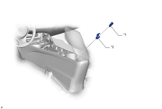
ILLUSTRATION
|
*1 |
NO. 1 POWER OUTLET SOCKET ASSEMBLY |
*2 |
NO. 1 POWER OUTLET SOCKET COVER |
Removal
REMOVAL
PROCEDURE
1. REMOVE NO. 2 CONSOLE BOX CUP HOLDER
Click here .gif)
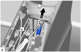
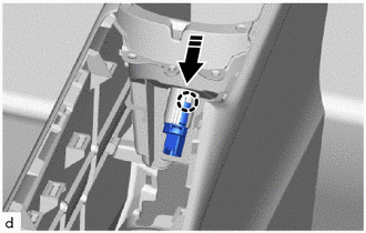
2. REMOVE NO. 1 POWER OUTLET SOCKET ASSEMBLY
(a) Disconnect the connector.
(b) Using a screwdriver with its tip wrapped in protective tape, disengage the claw to remove the No. 1 power outlet socket assembly as shown in the illustration.
|
*a |
Protective Tape |
.png) |
Remove in this Direction |
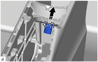
3. REMOVE NO. 1 POWER OUTLET SOCKET COVER
(a) Disengage the claws to remove the No. 1 power outlet socket cover as shown in the illustration.
|
|
Remove in this Direction |
Installation
INSTALLATION
PROCEDURE
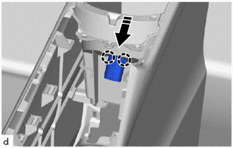
1. INSTALL NO. 1 POWER OUTLET SOCKET COVER
(a) Engage the claws to install the No. 1 power outlet socket cover as shown in the illustration.
.png) |
Install in this Direction |
2. INSTALL NO. 1 POWER OUTLET SOCKET ASSEMBLY
(a) Engage the claw to install the No. 1 power outlet socket assembly as shown in the illustration.
|
|
Install in this Direction |
(b) Connect the connector.
3. INSTALL NO. 2 CONSOLE BOX CUP HOLDER
Click here .gif)

 Pre-collision
...
Other materials:
Toyota CH-R Service Manual > Maintenance: 3zr-fae Spark Plug
Components
COMPONENTS
ILLUSTRATION
*1
IGNITION COIL ASSEMBLY
*2
NO. 2 CYLINDER HEAD COVER
*3
SPARK PLUG
-
-
N*m (kgf*cm, ft.*lbf): Specified torque
-
- ...
Toyota CH-R Service Manual > Vacuum Pump: Installation
INSTALLATION
PROCEDURE
1. INSTALL VACUUM PUMP ASSEMBLY
(a) When installing a new vacuum pump assembly:
(1) Apply engine oil to the No. 2 O-ring and No. 3 O-ring which are installed
to a new vacuum pump assembly.
...
Toyota C-HR (AX20) 2023-2026 Owner's Manual
Toyota CH-R Owners Manual
- For safety and security
- Instrument cluster
- Operation of each component
- Driving
- Interior features
- Maintenance and care
- When trouble arises
- Vehicle specifications
- For owners
Toyota CH-R Service Manual
- Introduction
- Maintenance
- Audio / Video
- Cellular Communication
- Navigation / Multi Info Display
- Park Assist / Monitoring
- Brake (front)
- Brake (rear)
- Brake Control / Dynamic Control Systems
- Brake System (other)
- Parking Brake
- Axle And Differential
- Drive Shaft / Propeller Shaft
- K114 Cvt
- 3zr-fae Battery / Charging
- Networking
- Power Distribution
- Power Assist Systems
- Steering Column
- Steering Gear / Linkage
- Alignment / Handling Diagnosis
- Front Suspension
- Rear Suspension
- Tire / Wheel
- Tire Pressure Monitoring
- Door / Hatch
- Exterior Panels / Trim
- Horn
- Lighting (ext)
- Mirror (ext)
- Window / Glass
- Wiper / Washer
- Door Lock
- Heating / Air Conditioning
- Interior Panels / Trim
- Lighting (int)
- Meter / Gauge / Display
- Mirror (int)
- Power Outlets (int)
- Pre-collision
- Seat
- Seat Belt
- Supplemental Restraint Systems
- Theft Deterrent / Keyless Entry

0.0065