Toyota CH-R Service Manual: Open in Turn Signal Circuit (B1507,B1508)
DESCRIPTION
These DTCs are stored when the combination meter assembly detects an open in a turn signal light circuit, or a short in a turn signal light circuit or the hazard warning light circuit.
|
DTC No. |
Detection Item |
DTC Detection Condition |
Trouble Area |
Memory |
Note |
|---|---|---|---|---|---|
|
B1507 |
Open in Turn Signal Circuit |
When IG voltage is 9.5 V or more and the following condition is detected:
|
|
DTC stored |
- |
|
B1508 |
Short in Turn Signal / Hazard Flasher Circuit |
When IG voltage is 9.5 V or more and the following condition is detected:
|
|
DTC stored |
- |
- *1: for Halogen Headlight Type
- *2: for LED Headlight Type
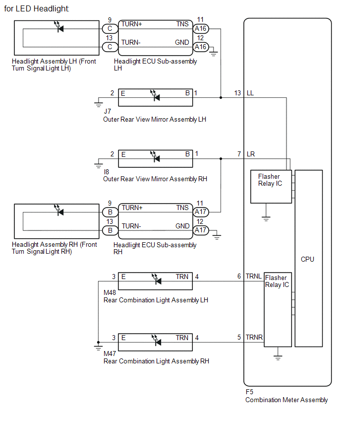
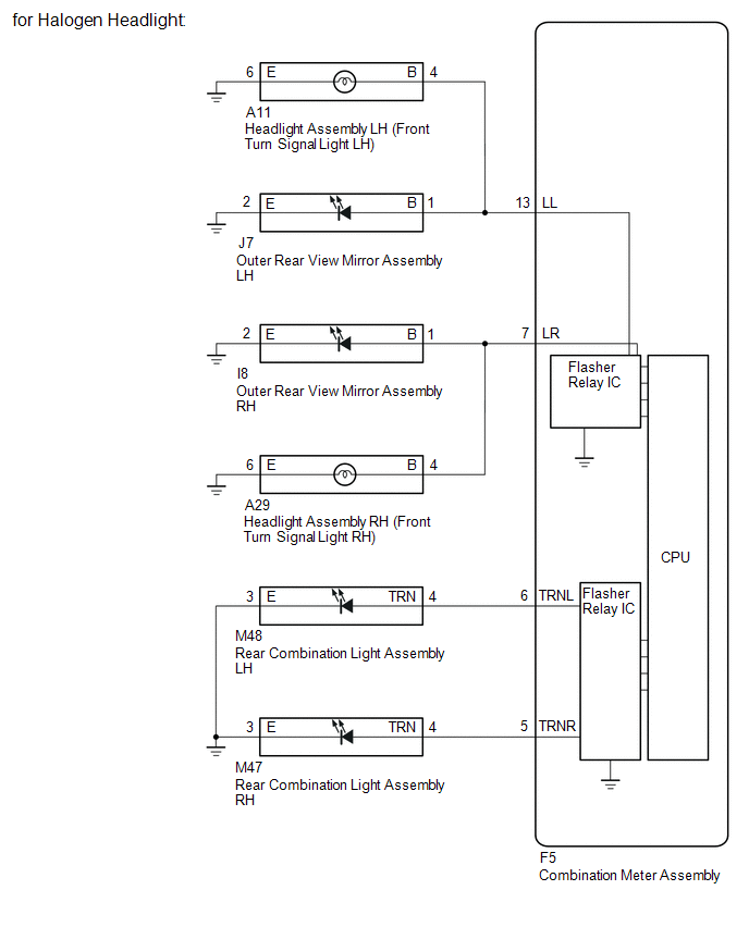
WIRING DIAGRAM
CAUTION / NOTICE / HINT
NOTICE:
- Inspect the LEDs and bulbs for this system before performing the following procedure.
- When replacing the combination meter assembly, always replace it with a new one. If a combination meter assembly which was installed to another vehicle is used, the information stored in it will not match the information from the vehicle and a DTC may be stored.
PROCEDURE
|
1. |
INSPECT LIGHTS |
(a) Inspect the illumination of each turn signal light.
|
Result |
Proceed to |
|---|---|
|
RH side turn signal light does not illuminate. |
A |
|
LH side turn signal light does not illuminate. |
B |
| B | .gif) |
GO TO STEP 8 |
|
.gif)
|
2. |
CHECK TURN SIGNAL LIGHTS (RH SIDE) |
(a) Turn the ignition switch ON.
(b) Set the headlight dimmer switch assembly to the right turn switch position.
(c) Check the operation of the turn signal lights (RH side).
|
Result |
Proceed to |
|---|---|
|
Front turn signal light assembly (RH side) does not blink. (for LED Headlight Type) |
A |
|
Front turn signal light assembly (RH side) does not blink. (for Halogen Headlight Type) |
B |
|
Side turn signal light assembly (RH side) does not blink. |
C |
|
Rear turn signal light assembly (RH side) does not blink. |
D |
| B | |
GO TO STEP 5 |
| C | |
GO TO STEP 6 |
| D | |
GO TO STEP 7 |
|
|
3. |
CHECK HARNESS AND CONNECTOR (HEADLIGHT ECU SUB-ASSEMBLY RH - COMBINATION METER ASSEMBLY OR BODY GROUND) |
(a) Disconnect the A17 headlight ECU sub-assembly RH connector.
(b) Disconnect the F5 combination meter assembly connector.
(c) Measure the resistance according to the value(s) in the table below.
Standard Resistance:
|
Tester Connection |
Condition |
Specified Condition |
|---|---|---|
|
A17-11 (TNS) - F5-7 (LR) |
Always |
Below 1 Ω |
|
A17-12 (GND) - Body ground |
Always |
Below 1 Ω |
|
A17-11 (TNS) - Body ground |
Always |
10 kΩ or higher |
| NG | |
REPAIR OR REPLACE HARNESS OR CONNECTOR |
|
|
4. |
INSPECT HEADLIGHT ECU SUB-ASSEMBLY RH |
(a) Remove the Headlight ECU sub-assembly RH.
Click here .gif)
|
(b) Measure the resistance according to the value(s) in the table below. Standard Resistance:
|
|
| OK | |
REPLACE COMBINATION METER ASSEMBLY |
| NG | |
REPLACE HEADLIGHT ECU SUB-ASSEMBLY RH |
|
5. |
CHECK HARNESS AND CONNECTOR (HEADLIGHT ASSEMBLY RH - COMBINATION METER ASSEMBLY OR BODY GROUND) |
(a) Disconnect the A29 headlight assembly RH connector.
(b) Disconnect the F5 combination meter assembly connector.
(c) Measure the resistance according to the value(s) in the table below.
Standard Resistance:
|
Tester Connection |
Condition |
Specified Condition |
|---|---|---|
|
A29-4 (B) - F5-7 (LR) |
Always |
Below 1 Ω |
|
A29-6 (E) - Body ground |
Always |
Below 1 Ω |
|
A29-4 (B) - Body ground |
Always |
10 kΩ or higher |
| OK | |
REPLACE COMBINATION METER ASSEMBLY |
| NG | |
REPAIR OR REPLACE HARNESS OR CONNECTOR |
|
6. |
CHECK HARNESS AND CONNECTOR (COMBINATION METER ASSEMBLY - OUTER REAR VIEW MIRROR ASSEMBLY RH) |
(a) Disconnect the F5 combination meter assembly connector.
(b) Disconnect the I8 outer rear view mirror assembly RH connector.
(c) Measure the resistance according to the value(s) in the table below.
Standard Resistance:
|
Tester Connection |
Condition |
Specified Condition |
|---|---|---|
|
F5-7 (LR) - I8-1 (B) |
Always |
Below 1 Ω |
|
I8-2 (E) - Body ground |
Always |
Below 1 Ω |
|
I8-1 (B) - Body ground |
Always |
10 kΩ or higher |
| OK | |
REPLACE COMBINATION METER ASSEMBLY |
| NG | |
REPAIR OR REPLACE HARNESS OR CONNECTOR |
|
7. |
CHECK HARNESS AND CONNECTOR (REAR COMBINATION LIGHT ASSEMBLY RH - COMBINATION METER ASSEMBLY OR BODY GROUND) |
(a) Disconnect the M47 rear combination light assembly RH connector.
(b) Disconnect the F5 combination meter assembly connector.
(c) Measure the resistance according to the value(s) in the table below.
Standard Resistance:
|
Tester Connection |
Condition |
Specified Condition |
|---|---|---|
|
M47-4 (TRN) - F5-5 (TRNR) |
Always |
Below 1 Ω |
|
M47-3 (E) - Body ground |
Always |
Below 1 Ω |
|
M47-4 (TRN) - Body ground |
Always |
10 kΩ or higher |
| OK | |
REPLACE COMBINATION METER ASSEMBLY |
| NG | |
REPAIR OR REPLACE HARNESS OR CONNECTOR |
|
8. |
CHECK TURN SIGNAL LIGHTS (LH SIDE) |
(a) Turn the ignition switch ON.
(b) Set the headlight dimmer switch assembly to the left turn switch position.
(c) Check the operation of the turn signal lights (LH side).
|
Result |
Proceed to |
|---|---|
|
Front turn signal light assembly (LH side) does not blink. (for LED Headlight Type) |
A |
|
Front turn signal light assembly (RH side) does not blink. (for Halogen Headlight Type) |
B |
|
Side turn signal light assembly (LH side) does not blink. |
C |
|
Rear turn signal light assembly (LH side) does not blink. |
D |
| B | |
GO TO STEP 11 |
| C | |
GO TO STEP 12 |
| D | |
GO TO STEP 13 |
|
|
9. |
CHECK HARNESS AND CONNECTOR (COMBINATION METER ASSEMBLY - HEADLIGHT ECU SUB-ASSEMBLY LH OR BODY GROUND) |
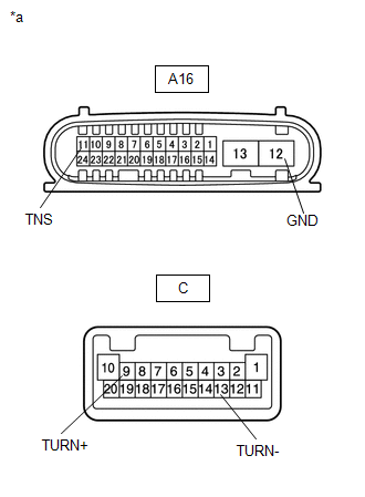
(a) Disconnect the A16 headlight ECU sub-assembly LH connector.
(b) Disconnect the F5 combination meter assembly connector.
(c) Measure the resistance according to the value(s) in the table below.
Standard Resistance:
|
Tester Connection |
Condition |
Specified Condition |
|---|---|---|
|
A16-11 (TNS) - F5-13 (LL) |
Always |
Below 1 Ω |
|
A16-12 (GND) - Body ground |
Always |
Below 1 Ω |
|
A16-11 (TNS) - Body ground |
Always |
10 kΩ or higher |
| NG | |
REPAIR OR REPLACE HARNESS OR CONNECTOR |
|
|
10. |
INSPECT HEADLIGHT ECU SUB-ASSEMBLY LH |
(a) Remove the Headlight ECU sub-assembly LH.
Click here
|
(b) Measure the resistance according to the value(s) in the table below. Standard Resistance:
|
|
| OK | |
REPLACE COMBINATION METER ASSEMBLY |
| NG | |
REPLACE HEADLIGHT ECU SUB-ASSEMBLY |
|
11. |
CHECK HARNESS AND CONNECTOR (HEADLIGHT ASSEMBLY LH - COMBINATION METER ASSEMBLY OR BODY GROUND) |
(a) Disconnect the A11 headlight assembly LH connector.
(b) Disconnect the F5 combination meter assembly connector.
(c) Measure the resistance according to the value(s) in the table below.
Standard Resistance:
|
Tester Connection |
Condition |
Specified Condition |
|---|---|---|
|
A11-4 (B) - F5-13 (LL) |
Always |
Below 1 Ω |
|
A11-6 (E) - Body ground |
Always |
Below 1 Ω |
|
A11-4 (B) - Body ground |
Always |
10 kΩ or higher |
| OK | |
REPLACE COMBINATION METER ASSEMBLY |
| NG | |
REPAIR OR REPLACE HARNESS OR CONNECTOR |
|
12. |
CHECK HARNESS AND CONNECTOR (COMBINATION METER ASSEMBLY - OUTER REAR VIEW MIRROR ASSEMBLY LH OR BODY GROUND) |
(a) Disconnect the F5 combination meter assembly connector.
(b) Disconnect the J7 outer rear view mirror assembly LH connector.
(c) Measure the resistance according to the value(s) in the table below.
Standard Resistance:
|
Tester Connection |
Condition |
Specified Condition |
|---|---|---|
|
J7-1 (B) - F5-13 (LL) |
Always |
Below 1 Ω |
|
J7-2 (E) - Body ground |
Always |
Below 1 Ω |
|
J7-1 (B) - Body ground |
Always |
10 kΩ or higher |
| OK | |
REPLACE COMBINATION METER ASSEMBLY |
| NG | |
REPAIR OR REPLACE HARNESS OR CONNECTOR |
|
13. |
CHECK HARNESS AND CONNECTOR (REAR COMBINATION LIGHT ASSEMBLY LH - COMBINATION METER ASSEMBLY OR BODY GROUND) |
(a) Disconnect the M48 rear combination light assembly LH connector.
(b) Disconnect the F5 combination meter assembly connector.
(c) Measure the resistance according to the value(s) in the table below.
Standard Resistance:
|
Tester Connection |
Condition |
Specified Condition |
|---|---|---|
|
F5-6 (TRNL) - M48-4 (TRN) |
Always |
Below 1 Ω |
|
M48-3 (E) - Body ground |
Always |
Below 1 Ω |
|
M48-4 (TRN) - Body ground |
Always |
10 kΩ or higher |
| OK | |
REPLACE COMBINATION METER ASSEMBLY |
| NG | |
REPAIR OR REPLACE HARNESS OR CONNECTOR |
 On-vehicle Inspection
ON-VEHICLE INSPECTION
PROCEDURE
1. INSPECT COMBINATION METER ASSEMBLY
(a) Check speedometer operation
NOTICE:
The combination meter assembly receives the vehicle speed signal from
the ...
 Lost Communication with ECM / PCM "A" (U0100,U0129,U0131,U0142,U0151,U0182,U0235,U023A)
DESCRIPTION
The combination meter assembly communicates with the ECM, brake actuator assembly
(skid control ECU), power steering ECU assembly, main body ECU (multiplex network
body ECU), airbag s ...
Other materials:
Toyota CH-R Service Manual > Steering Gear: Reassembly
REASSEMBLY
PROCEDURE
1. INSTALL NO. 2 STEERING RACK BOOT
(a) Apply lithium soap base glycol grease to the inside of the small
opening of a new No. 2 steering rack boot.
(b) Install the No. 2 steering rack boot to the groove on the ra ...
Toyota CH-R Service Manual > Can Communication System: Check Bus 3 Line for Short to GND
DESCRIPTION
There may be a short circuit between one of the CAN bus lines and GND when there
is no resistance between terminal 6 (CA3H) of the central gateway ECU (network gateway
ECU) and terminal 4 (CG) of the DLC3, or terminal 21 (CA3L) of the central gateway
ECU (network gateway ECU) and ...
Toyota C-HR (AX20) 2023-2026 Owner's Manual
Toyota CH-R Owners Manual
- For safety and security
- Instrument cluster
- Operation of each component
- Driving
- Interior features
- Maintenance and care
- When trouble arises
- Vehicle specifications
- For owners
Toyota CH-R Service Manual
- Introduction
- Maintenance
- Audio / Video
- Cellular Communication
- Navigation / Multi Info Display
- Park Assist / Monitoring
- Brake (front)
- Brake (rear)
- Brake Control / Dynamic Control Systems
- Brake System (other)
- Parking Brake
- Axle And Differential
- Drive Shaft / Propeller Shaft
- K114 Cvt
- 3zr-fae Battery / Charging
- Networking
- Power Distribution
- Power Assist Systems
- Steering Column
- Steering Gear / Linkage
- Alignment / Handling Diagnosis
- Front Suspension
- Rear Suspension
- Tire / Wheel
- Tire Pressure Monitoring
- Door / Hatch
- Exterior Panels / Trim
- Horn
- Lighting (ext)
- Mirror (ext)
- Window / Glass
- Wiper / Washer
- Door Lock
- Heating / Air Conditioning
- Interior Panels / Trim
- Lighting (int)
- Meter / Gauge / Display
- Mirror (int)
- Power Outlets (int)
- Pre-collision
- Seat
- Seat Belt
- Supplemental Restraint Systems
- Theft Deterrent / Keyless Entry

0.0092