Toyota CH-R Service Manual: Terminals Of Ecu
TERMINALS OF ECU
COMBINATION METER ASSEMBLY
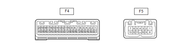
(a) Disconnect the combination meter assembly connectors.
(b) Measure the voltage on the wire harness side connector according to the value(s) in the table below.
|
Terminal No. |
Wiring Color |
Terminal Description |
Condition |
Specified Condition |
|---|---|---|---|---|
|
F4-39 (IG+) - Body ground |
P - Body ground |
Ignition switch signal |
Ignition switch off |
Below 1 V |
|
Ignition switch ON |
11 to 14 V |
|||
|
F4-40 (B) - Body ground |
SB - Body ground |
Battery |
Always |
11 to 14 V |
|
F5-1 (B) - Body ground |
SB - Body ground |
Battery |
Always |
11 to 14 V |
If the result is not as specified, there may be a malfunction in the wire harness.
(c) Reconnect the combination meter assembly connectors.
(d) Measure the voltage and resistance according to the value(s) in the table below.
|
Terminal No. (Symbol) |
Wiring Color |
Terminal Description |
Condition |
Specified Condition |
|---|---|---|---|---|
|
F4-1 (RLMT) - Body ground*1 |
L - Body ground |
Rear seat belt LH warning light signal |
Rear seat belt LH fastened within 30 seconds of opening rear door with ignition switch ON |
11 to 14 V |
|
Rear seat belt LH unfastened within 30 seconds of opening rear door with ignition switch ON |
Below 1 V |
|||
|
F4-2 (RCMT) - Body ground*1 |
V - Body ground |
Rear seat center belt warning light signal |
Rear seat center belt fastened within 30 seconds of opening rear door with ignition switch ON |
11 to 14 V |
|
Rear seat center belt unfastened within 30 seconds of opening rear door with ignition switch ON |
Below 1 V |
|||
|
F4-3 (RRMT) - Body ground*1 |
W - Body ground |
Rear seat belt RH warning light signal |
Rear seat belt RH fastened within 30 seconds of opening rear door with ignition switch ON |
11 to 14 V |
|
Rear seat belt RH unfastened within 30 seconds of opening rear door with ignition switch ON |
Below 1 V |
|||
|
F4-4 (INT) - Body ground*2 |
B - Body ground |
Tire pressure warning light signal |
Ignition switch ON, tire pressure warning light off |
Below 1 V |
|
Ignition switch ON, tire pressure warning light on |
11 to 14 V |
|||
|
F4-5 (SI) - Body ground |
GR - Body ground |
Speed signal for other system (Input) |
Ignition switch ON, wheel being rotated |
Pulse generation (See waveform 1) |
|
F4-6 (+S) - Body ground |
V - Body ground |
Speed signal for other system (Output) |
Ignition switch ON, wheel being rotated |
Pulse generation (See waveform 1) |
|
F4-7 (PKBI) - Body ground*3 |
GR - Body ground |
Front passenger side seat belt buckle switch signal |
Ignition switch ON, front passenger side seat belt fastened and front passenger seat occupied |
11 to 14 V |
|
Ignition switch ON, front passenger side seat belt unfastened and front passenger seat occupied |
Below 1 V |
|||
|
F4-9 (S) - Body ground |
G - Body ground |
Engine oil pressure switch signal |
Ignition switch ON, low engine oil level warning light on |
Below 1 V |
|
Ignition switch ON, low engine oil level warning light off |
11 to 14 V |
|||
|
F4-10 (MSD) - Body ground*1 |
V - Body ground |
Rear seat inner belt signal (LH side) |
Ignition switch ON, rear LH seat belt unfastened |
Below 1 V |
|
Ignition switch ON, rear LH seat belt fastened |
11 to 14 V |
|||
|
F4-11 (MSTI) - Body ground*1 |
BE - Body ground |
Rear seat inner belt signal (Center) |
Ignition switch ON, rear center seat belt unfastened |
Below 1 V |
|
Ignition switch ON, rear center seat belt fastened |
11 to 14 V |
|||
|
F4-12 (SW) - Body ground |
R - Body ground |
Brake system warning light (red indicator) signal |
Ignition switch ON, brake system warning light (red indicator) on |
Below 1 V |
|
Ignition switch ON, brake system warning light (red indicator) off |
11 to 14 V |
|||
|
F4-13 (MSFM) - Body ground*1 |
R - Body ground |
Rear seat inner belt signal (RH side) |
Ignition switch ON, rear RH seat belt unfastened |
Below 1 V |
|
Ignition switch ON, rear RH seat belt fastened |
11 to 14 V |
|||
|
F4-16 (FV) - Body ground |
GR - Body ground |
Fuel sender gauge (Power source) |
Fuel F (full tank) → E (empty) |
4.5 to 5.5 V |
|
F4-17 (WLVL) - Body ground*4 |
LG - Body ground |
Washer fluid level signal |
Ignition switch ON washer fluid level not low |
11 to 14 V |
|
Ignition switch ON washer fluid level low |
Below 1 V |
|||
|
F4-20 (SW3) - Body Ground |
W - Body ground |
Light control rheostat switch ground |
Always |
Below 1 Ω |
|
F4-21 (ET) - Body ground |
W-B - Body ground |
Ground |
Always |
Below 1 Ω |
|
F4-23 (FR) - F4-15 (FE&B) |
G - BE |
Fuel level signal |
Ignition switch ON fuel level full |
Below 1 V |
|
Ignition switch ON fuel level low (fuel level warning light on) |
4.5 to 9 V |
|||
|
F4-24 (TC) - Body Ground |
V - Body ground |
TAIL cancel switch signal |
TAIL cancel switch OFF → ON |
10 kΩ or higher → Below 1 Ω |
|
F4-25 (SW1) - Body Ground |
G - Body ground |
Power source for light control rheostat |
Ignition switch ON |
4.6 to 5.4 V |
|
F4-26 (SW2) - Body Ground |
L - Body ground |
Light control rheostat knob input |
Light control rheostat knob fully turned downward |
Below 1 Ω |
|
Light control rheostat knob fully turned upward |
10 kΩ or higher |
|||
|
F4-28 (MSM+) - Body ground |
V - Body ground |
Steering pad switch signal |
Ignition switch ON, enter, trip and back switches on steering pad switch not pushed |
4.3 to 5.2 V |
|
Ignition switch ON, enter switch on steering pad switch pushed |
Below 0.6 V |
|||
|
Ignition switch ON, trip switch on steering pad switch pushed |
1.0 to 2.2 V |
|||
|
Ignition switch ON, back switch on steering pad switch pushed |
2.3 to 3.4 V |
|||
|
F4-31 (CANL) - Body ground |
SB - Body ground |
CAN communication line |
- |
- |
|
F4-32 (CANH) - Body ground |
V - Body ground |
CAN communication line |
- |
- |
|
F4-33 (MSSL) - Body ground |
GR - Body ground |
Steering pad switch signal |
Ignition switch ON, up, down, right and left switches on steering pad switch assembly not pushed |
4.3 to 5.2 V |
|
Ignition switch ON, left switch on steering pad switch pushed |
Below 0.6 V |
|||
|
Ignition switch ON, up switch on steering pad switch pushed |
1.0 to 2.2 V |
|||
|
Ignition switch ON, down switch on steering pad switch pushed |
2.3 to 3.4 V |
|||
|
Ignition switch ON, right switch on steering pad switch pushed |
3.4 to 4.5 V |
|||
|
F4-34 (TEMP) - Body ground |
SB - Body ground |
Ambient temperature sensor signal |
Ambient temperature 25°C (77°F) |
1.6 to 1.8 Ω |
|
F4-35 (TX1+) - Body ground |
P - Body ground |
Ambient temperature sensor gauge signal |
Always |
Below 1 Ω |
|
F5-2 (VCM) - Body ground*5 |
GR - Body ground |
Vacuum warning switch signal |
Ignition switch ON, engine idle speed |
Pulse generation |
|
F5-3 (HAZ) - Body ground |
W - Body ground |
Hazard warning signal switch signal (Output) |
Hazard warning signal switch off |
11 to 14 V |
|
Hazard warning signal switch on |
Below 1 V |
|||
|
F5-5 (TRNR) - Body ground |
SB - Body ground |
Rear turn signal light RH signal |
Ignition switch ON, RH turn indicator light off |
Below 1 V |
|
Ignition switch ON, RH turn indicator light blinking |
11 to 14 V ←→ Below 1 V |
|||
|
F5-6 (TRNL) - Body ground |
Y - Body ground |
Rear turn signal light LH signal |
Ignition switch ON, LH turn indicator light off |
Below 1 V |
|
Ignition switch ON, LH turn indicator light blinking |
11 to 14 V ←→ Below 1 V |
|||
|
F5-7 (LR) - Body ground |
V - Body ground |
Rear turn signal light RH signal |
Ignition switch ON, RH turn indicator light off |
Below 1 V |
|
Ignition switch ON, RH turn indicator light blinking |
11 to 14 V ←→ Below 1 V |
|||
|
F5-8 (SW) - Body ground |
L - Body ground |
Turn signal switch (full turn) signal |
Headlight dimmer switch on (full turn) |
Below 1 V |
|
Headlight dimmer switch off |
11 to 14 V |
|||
|
F5-9 (ER) - Body ground |
P - Body ground |
RH turn indicator light signal (Input) |
Ignition switch ON, RH turn signal switch on |
Below 1 V |
|
Ignition switch ON, RH turn signal switch off |
11 to 14 V |
|||
|
F5-10 (EL) - Body ground |
B - Body ground |
LH turn indicator light signal (Input) |
Ignition switch ON, LH turn signal switch on |
Below 1 V |
|
Ignition switch ON, LH turn signal switch off |
11 to 14 V |
|||
|
F5-13 (LL) - Body ground |
G - Body ground |
Rear turn signal light LH signal |
Ignition switch ON, LH turn indicator light off |
Below 1 V |
|
Ignition switch ON, LH turn indicator light blinking |
11 to 14 V ←→ Below 1 V |
- *1: w/ Rear Passenger Seat Belt Warning
- *2: w/ Tire Pressure Warning System
- *3: w/o Occupant Classification System
- *4: w/ Washer Level Warning Switch
- *5: w/ Vacuum Warning Switch
If the result is not as specified, the combination meter assembly may be malfunctioning.
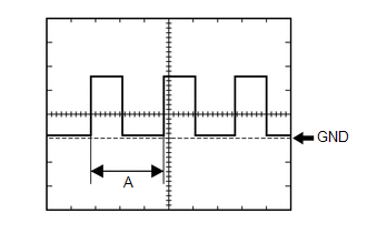
(1) Waveform 1 (Reference):
|
Item |
Condition |
|---|---|
|
Tool setting |
5 V/DIV., 20 ms./DIV. |
|
Vehicle condition |
Ignition switch ON wheel being rotated |
HINT:
When the system is functioning normally, one wheel revolution generates 4 pulses. As the vehicle speed increases, the width indicated by (A) in the illustration narrows.
 Problem Symptoms Table
PROBLEM SYMPTOMS TABLE
NOTICE:
When replacing the combination meter assembly, always replace it with a new one.
If a combination meter assembly which was installed to another vehicle is used,
th ...
 Data List / Active Test
DATA LIST / ACTIVE TEST
DATA LIST
NOTICE:
In the table below, the values listed under "Normal Condition" are reference
values. Do not depend solely on these reference values when decidi ...
Other materials:
Toyota CH-R Service Manual > Steering Lock System: Steering Lock does not Lock
DESCRIPTION
The steering lock actuator or upper bracket assembly activates the steering lock
motor and moves the lock bar into the steering column to lock the steering.
When the steering lock is operating, the steering may not lock when the lock
bar is not aligned with the lock hole of the ste ...
Toyota CH-R Service Manual > Front Door Lock: Inspection
INSPECTION
PROCEDURE
1. INSPECT FRONT DOOR LOCK WITH MOTOR ASSEMBLY LH (w/o Double Locking System)
(a) Check the door lock motor operation (for Driver Side).
(1) Apply battery voltage to the motor connector and check the operation
of the door lock motor.
OK:
...
Toyota C-HR (AX20) 2023-2026 Owner's Manual
Toyota CH-R Owners Manual
- For safety and security
- Instrument cluster
- Operation of each component
- Driving
- Interior features
- Maintenance and care
- When trouble arises
- Vehicle specifications
- For owners
Toyota CH-R Service Manual
- Introduction
- Maintenance
- Audio / Video
- Cellular Communication
- Navigation / Multi Info Display
- Park Assist / Monitoring
- Brake (front)
- Brake (rear)
- Brake Control / Dynamic Control Systems
- Brake System (other)
- Parking Brake
- Axle And Differential
- Drive Shaft / Propeller Shaft
- K114 Cvt
- 3zr-fae Battery / Charging
- Networking
- Power Distribution
- Power Assist Systems
- Steering Column
- Steering Gear / Linkage
- Alignment / Handling Diagnosis
- Front Suspension
- Rear Suspension
- Tire / Wheel
- Tire Pressure Monitoring
- Door / Hatch
- Exterior Panels / Trim
- Horn
- Lighting (ext)
- Mirror (ext)
- Window / Glass
- Wiper / Washer
- Door Lock
- Heating / Air Conditioning
- Interior Panels / Trim
- Lighting (int)
- Meter / Gauge / Display
- Mirror (int)
- Power Outlets (int)
- Pre-collision
- Seat
- Seat Belt
- Supplemental Restraint Systems
- Theft Deterrent / Keyless Entry

0.01