Toyota CH-R Service Manual: 3zr-fae Spark Plug
Components
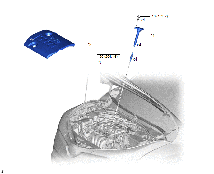
COMPONENTS
ILLUSTRATION
|
*1 |
IGNITION COIL ASSEMBLY |
*2 |
NO. 2 CYLINDER HEAD COVER |
|
*3 |
SPARK PLUG |
- |
- |
.png) |
N*m (kgf*cm, ft.*lbf): Specified torque |
- |
- |
Removal
REMOVAL
CAUTION / NOTICE / HINT
The necessary procedures (adjustment, calibration, initialization, or registration) that must be performed after parts are removed, installed, or replaced during the ignition coil assembly or spark plug removal/installation are shown below.
Necessary Procedure After Parts Removed/Installed/Replaced|
Replacement Part or Procedure |
Necessary Procedure |
Effect/Inoperative when not Performed |
Link |
|---|---|---|---|
|
Replacement of ignition coil assembly |
Inspection after repair |
|
|
|
Replacement of spark plug |
PROCEDURE
1. REMOVE NO. 2 CYLINDER HEAD COVER
Click here
.gif)
2. REMOVE IGNITION COIL ASSEMBLY
Click here
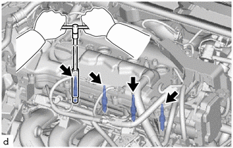
3. REMOVE SPARK PLUG
|
(a) Remove the 4 spark plugs from the cylinder head sub-assembly. NOTICE: If a spark plug has been struck or dropped, replace it. HINT: Arrange the removed parts in the correct order. |
|
Installation
INSTALLATION
PROCEDURE
1. INSTALL SPARK PLUG
HINT:
Perform "Inspection After Repair" after replacing a spark plug.
- w/ Canister Pump Module:
Click here
.gif)
- w/o Canister Pump Module:
Click here
(a) Install the 4 spark plugs to the cylinder head sub-assembly.
Torque:
20 N·m {204 kgf·cm, 15 ft·lbf}
NOTICE:
If a spark plug has been struck or dropped, replace it.
HINT:
Install the same parts to their original positions.
2. INSTALL IGNITION COIL ASSEMBLY
Click here
3. INSTALL NO. 2 CYLINDER HEAD COVER
Click here
4. PERFORM INITIALIZATION
(a) Perform "Inspection After Repair" after replacing a spark plug or ignition coil assembly.
- w/ Canister Pump Module:
Click here
- w/o Canister Pump Module:
Click here
 Replacement
REPLACEMENT
CAUTION / NOTICE / HINT
CAUTION:
Prolonged and repeated contact with engine oil will result in the removal
of natural oils from the skin, leading to dryness, irritation and ...
 Air Conditioning Filter(for Denso Made)
Components
COMPONENTS
ILLUSTRATION
*1
AIR FILTER COVER PLATE
*2
CLEAN AIR FILTER
*3
GLOVE COMPARTMENT DOOR ASSEMBLY
...
Other materials:
Toyota CH-R Service Manual > Lighting System: Clearance Light/Daytime Running Light Circuit
DESCRIPTION
Clearance light function:
When the main body ECU (multiplex network body ECU) receives the light
control switch position signal, it sends an illumination request signal
to the headlight ECU sub-assembly LH and illuminates the clearance lights.
Daytime runni ...
Toyota CH-R Service Manual > Pre-collision System: Heater Circuit (C1AAE)
DESCRIPTION
The forward recognition camera controls the current supplied to the pre-collision
city heater (forward recognition hood).
DTC No.
Detection Item
DTC Detection Condition
Trouble Area
C1AAE
Heater Circuit
...
Toyota C-HR (AX20) 2023-2026 Owner's Manual
Toyota CH-R Owners Manual
- For safety and security
- Instrument cluster
- Operation of each component
- Driving
- Interior features
- Maintenance and care
- When trouble arises
- Vehicle specifications
- For owners
Toyota CH-R Service Manual
- Introduction
- Maintenance
- Audio / Video
- Cellular Communication
- Navigation / Multi Info Display
- Park Assist / Monitoring
- Brake (front)
- Brake (rear)
- Brake Control / Dynamic Control Systems
- Brake System (other)
- Parking Brake
- Axle And Differential
- Drive Shaft / Propeller Shaft
- K114 Cvt
- 3zr-fae Battery / Charging
- Networking
- Power Distribution
- Power Assist Systems
- Steering Column
- Steering Gear / Linkage
- Alignment / Handling Diagnosis
- Front Suspension
- Rear Suspension
- Tire / Wheel
- Tire Pressure Monitoring
- Door / Hatch
- Exterior Panels / Trim
- Horn
- Lighting (ext)
- Mirror (ext)
- Window / Glass
- Wiper / Washer
- Door Lock
- Heating / Air Conditioning
- Interior Panels / Trim
- Lighting (int)
- Meter / Gauge / Display
- Mirror (int)
- Power Outlets (int)
- Pre-collision
- Seat
- Seat Belt
- Supplemental Restraint Systems
- Theft Deterrent / Keyless Entry

0.0073