Toyota CH-R Service Manual: Installation
INSTALLATION
PROCEDURE
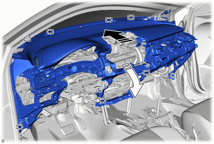
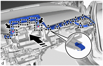
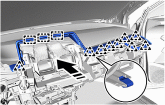
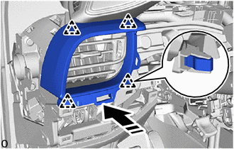
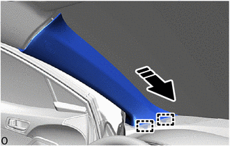
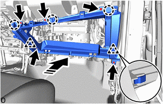
1. INSTALL INSTRUMENT PANEL SAFETY PAD SUB-ASSEMBLY
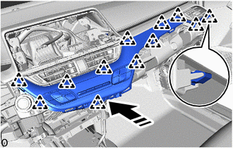
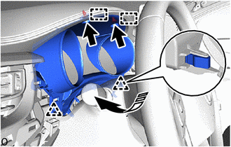
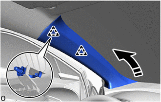
(a) Engage the guides to install the instrument panel safety pad sub-assembly as shown in the illustration.
.png) |
Install in this Direction (1) |
.png) |
Install in this Direction (2) |
(b) Engage each clamp.
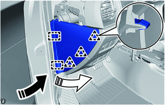
(c) Connect each connector.
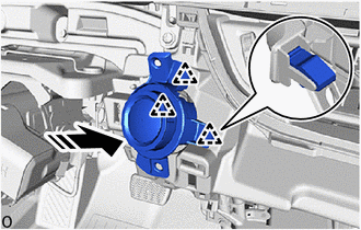
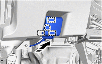
(d) Connect the airbag connector.
.png)
|
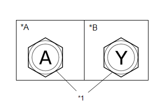
*a |
Airbag Connector |
*b |
Airbag Bolt |
|
*c |
Ground Bolt A |
*d |
Ground Bolt B |
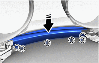
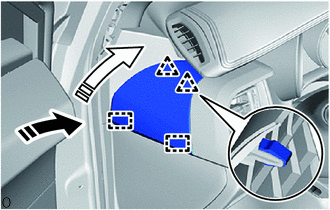
(e) Install the 4 clips.
(f) for TMMT Made:
|
(1) Install the 10 bolts as shown in the illustration. Torque: Airbag bolt : 20 N·m {204 kgf·cm, 15 ft·lbf} Ground bolt A, for Type A : 10.5 N·m {107 kgf·cm, 8 ft·lbf} Ground bolt A, for Type B : 10 N·m {102 kgf·cm, 7 ft·lbf} Ground bolt B, for Type A : 8.3 N·m {85 kgf·cm, 73 in·lbf} Ground bolt B, for Type B : 10 N·m {102 kgf·cm, 7 ft·lbf} |
|
(g) for TMC Made:
(1) Install the 10 bolts as shown in the illustration.
Torque:
Airbag bolt :
20 N·m {204 kgf·cm, 15 ft·lbf}
Ground bolt A :
10 N·m {102 kgf·cm, 7 ft·lbf}
Ground bolt B :
10 N·m {102 kgf·cm, 7 ft·lbf}
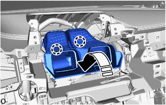
2. INSTALL NO. 2 HEATER TO REGISTER DUCT SUB-ASSEMBLY
(a) Engage the claws to install the No. 2 heater to register duct sub-assembly as shown in the illustration.
|
|
Install in this Direction |
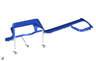
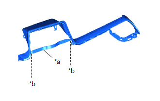
3. INSTALL NO. 1 INSTRUMENT PANEL GARNISH SUB-ASSEMBLY (w/ Display)
|
(a) When installing a new No. 1 instrument panel garnish sub-assembly: (1) Using a nipper, cut off both ends of the runner portion as shown in the illustration. |
|
(b) Engage the guides and clips to install the No. 1 instrument panel garnish sub-assembly as shown in the illustration.
|
|
Install in this Direction |
(c) Install the 2 bolts <G>.
4. INSTALL RADIO AND DISPLAY RECEIVER ASSEMBLY WITH BRACKET (for Radio and Display Type)
Click here .gif)
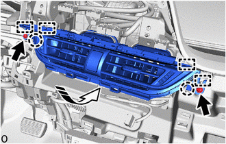
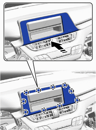
5. INSTALL INSTRUMENT PANEL CENTER REGISTER ASSEMBLY
(a) Engage the guides and claws to install the instrument panel center register assembly as shown in the illustration.
|
|
Install in this Direction |
(b) Install the 2 screws <D>.
6. INSTALL NO. 1 INSTRUMENT PANEL GARNISH SUB-ASSEMBLY (w/o Display)
|
(a) When installing a new No. 1 instrument panel garnish sub-assembly: (1) Using a nipper, cut off both ends of the runner portion as shown in the illustration. |
|
(b) Engage the guides and clips to install the No. 1 instrument panel garnish sub-assembly as shown in the illustration.
|
|
Install in this Direction |
7. INSTALL STARTER SWITCH BEZEL (w/ Smart Key System)
(a) Connect the connector.
(b) Engage the clips to install the starter switch bezel as shown in the illustration.
|
|
Install in this Direction |
8. INSTALL INSTRUMENT CLUSTER FINISH LOWER CENTER PANEL SUB-ASSEMBLY
(a) Connect the connector.
(b) Engage the clips to install the instrument cluster finish lower center panel sub-assembly as shown in the illustration.
|
|
Install in this Direction |
9. INSTALL NO. 1 RADIO BRACKET (w/o Radio Receiver)
|
(a) Engage the guides to install the No. 1 radio bracket. |
|
.png)
(b) Install the 3 screws <D>.
10. INSTALL NO. 2 RADIO BRACKET (w/o Radio Receiver)
|
(a) Engage the guides to install the No. 2 radio bracket. |
|
.png)
(b) Install the 3 screws <D>.
11. INSTALL STEREO OPENING COVER WITH BRACKET (w/o Radio Receiver)
(a) Connect the connector.
|
(b) Engage the guides to install the stereo opening cover with bracket. |
|
.png)
(c) Install the 4 bolts <G>.
12. INSTALL RADIO RECEIVER ASSEMBLY WITH BRACKET (w/ Radio Receiver)
Click here
13. INSTALL INSTRUMENT CLUSTER FINISH CENTER PANEL SUB-ASSEMBLY (w/o Display)
(a) Connect the connector.
(b) Engage the claws to install the instrument cluster finish center panel sub-assembly as shown in the illustration.
|
|
Install in this Direction |
14. INSTALL LOWER NO. 1 INSTRUMENT PANEL AIRBAG ASSEMBLY WITH DOOR
Click here
15. INSTALL FUSE BOX OPENING COVER
(a) Connect each connector.
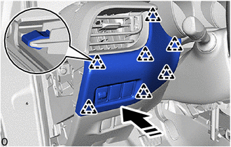
(b) Engage the clips to install the fuse box opening cover as shown in the illustration.
|
|
Install in this Direction |
(c) Install the screw <D>.
16. CONNECT HOOD LOCK CONTROL LEVER SUB-ASSEMBLY
(a) Engage the guides and claw to connect the hood lock control lever sub-assembly as shown in the illustration.
|
|
Install in this Direction |
17. INSTALL COMBINATION METER ASSEMBLY
Click here
18. INSTALL NO. 2 INSTRUMENT PANEL GARNISH SUB-ASSEMBLY
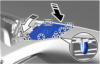
(a) Engage the clips to install the No. 2 instrument panel garnish sub-assembly as shown in the illustration.
|
|
Install in this Direction |
19. INSTALL INSTRUMENT CLUSTER FINISH PANEL ASSEMBLY
(a) Engage the guides and clips to install the instrument cluster finish panel assembly as shown in the illustration.
|
|
Install in this Direction |
(b) Install the 2 clips.
(c) Engage the claws to install the meter hood spacer as shown in the illustration.
|
|
Install in this Direction |
20. INSTALL INSTRUMENT CLUSTER FINISH PANEL SUB-ASSEMBLY
(a) w/ Switch:
(1) Connect each connector.
(b) Engage the clips to install the instrument cluster finish panel sub-assembly as shown in the illustration.
|
|
Install in this Direction |
21. INSTALL NO. 1 INSTRUMENT PANEL SPEAKER PANEL SUB-ASSEMBLY
(a) Connect the connector.
(b) Engage the guides, claws and clips to install the No. 1 instrument panel speaker panel sub-assembly as shown in the illustration.
|
|
Install in this Direction (1) |
|
|
Install in this Direction (2) |
22. INSTALL NO. 2 INSTRUMENT PANEL SPEAKER PANEL SUB-ASSEMBLY
HINT:
Use the same procedure as for the No. 1 instrument panel speaker panel sub-assembly side.
23. INSTALL FRONT PILLAR GARNISH LH
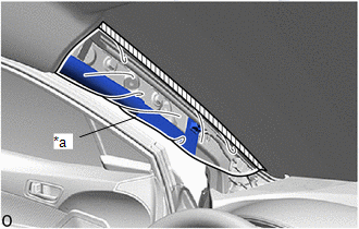
(a) Remove the adhesive tape and protective cover.
|
*a |
Protective Cover |
.png) |
Adhesive Tape |
|
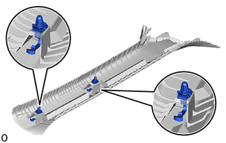
(b) Install the 2 front pillar garnish clips to the front pillar garnish LH. NOTICE:
|
|
(c) Engage the guides as shown in the illustration.
|
|
Install in this Direction |
(d) Engage the clips to install the front pillar garnish LH as shown in the illustration.
|
|
Install in this Direction |
24. INSTALL FRONT PILLAR GARNISH RH
HINT:
Use the same procedure as for the LH side.
25. INSTALL INSTRUMENT SIDE PANEL LH
(a) w/ Airbag Cut Off Switch:
(1) Connect the connector.
(b) Engage the guides and clips to install the instrument side panel LH as shown in the illustration.
|
|
Install in this Direction (1) |
|
|
Install in this Direction (2) |
26. INSTALL INSTRUMENT SIDE PANEL RH
HINT:
Use the same procedure as for the LH side.
27. INSTALL INSTRUMENT PANEL FINISH END PANEL LH
(a) Engage the guides and clips to install the instrument panel finish end panel LH as shown in the illustration.
|
|
Install in this Direction (1) |
|
|
Install in this Direction (2) |
28. INSTALL INSTRUMENT PANEL FINISH END PANEL RH
HINT:
Use the same procedure as for the LH side.
29. CONNECT FRONT DOOR OPENING TRIM WEATHERSTRIP LH
|
(a) Connect the front door opening trim weatherstrip LH to the area shown in the illustration. |
|
.png)
30. CONNECT FRONT DOOR OPENING TRIM WEATHERSTRIP RH
HINT:
Use the same procedure as for the LH side.
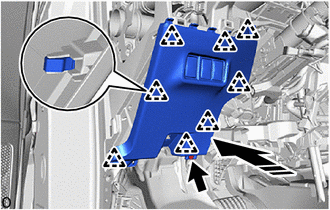
31. INSTALL NO. 2 INSTRUMENT PANEL LOWER FINISH PANEL
(a) Connect the connector.
(b) Engage the clips and claws to install the No. 2 instrument panel lower finish panel as shown in the illustration.
|
|
Install in this Direction |
(c) Install the 5 screws <D>.
32. INSTALL GLOVE COMPARTMENT DOOR STOPPER SUB-ASSEMBLY
|
(a) Engage the claw to install the glove compartment door stopper sub-assembly. |
|
.png)
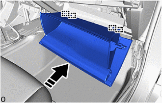
33. INSTALL GLOVE COMPARTMENT DOOR ASSEMBLY
(a) With the glove compartment door assembly opened approximately 61° from its closed position, engage the 4 hinges horizontally.
|
|
Install in this Direction |
NOTICE:
- Engaging the hinges from the top will deform the hinges.
- Be sure to install the glove compartment door assembly horizontally.
|
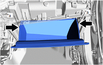
(b) While pushing in the sides of the glove compartment door assembly as indicated by the arrows in the illustration, close the door to engage it to the 2 stoppers. |
|
|
(c) Engage the claw to connect the glove compartment door stopper sub-assembly. |
|
.png)
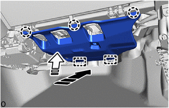
34. INSTALL NO. 2 INSTRUMENT PANEL UNDER COVER SUB-ASSEMBLY
(a) Engage the guides and claws to install the No. 2 instrument panel under cover sub-assembly as shown in the illustration.
|
|
Install in this Direction (1) |
|
|
Install in this Direction (2) |
35. INSTALL COWL SIDE TRIM BOARD RH
HINT:
Use the same procedure as for the LH side.
Click here
36. INSTALL FRONT DOOR SCUFF PLATE RH
HINT:
Use the same procedure as for the LH side.
Click here
37. INSTALL HEADLIGHT DIMMER SWITCH ASSEMBLY
Click here
38. INSTALL REAR CONSOLE BOX ASSEMBLY
Click here
39. CONNECT CABLE TO NEGATIVE BATTERY TERMINAL
Click here
NOTICE:
When disconnecting the cable, some systems need to be initialized after the cable is reconnected.
Click here
40. INSPECT SRS WARNING LIGHT
Click here
 Reassembly
REASSEMBLY
PROCEDURE
1. INSTALL NO. 1 INSTRUMENT PANEL CUSHION
(a) Install a new instrument panel cushion as shown in the illustration.
Standard Measurement:
Area ...
 Rear Console Box
...
Other materials:
Toyota CH-R Service Manual > Automatic High Beam System: Fail-safe Chart
FAIL-SAFE CHART
AUTOMATIC HIGH BEAM SYSTEM
(a) The main body ECU (multiplex network body ECU) operates in fail-safe mode
if an abnormal condition such as those listed below has been detected.
Item
Abnormality Detection Condition
Return Condition
Warni ...
Toyota CH-R Service Manual > Wiper And Washer System: Fail-safe Chart
FAIL-SAFE CHART
RAIN SENSOR FAIL-SAFE FUNCTION
(a) The windshield wiper switch assembly performs the fail-safe function when
the wiper system cannot properly receive the necessary signals for wiper system
control or a wiper system component is malfunctioning.
Item
Fail-s ...
Toyota C-HR (AX20) 2023-2026 Owner's Manual
Toyota CH-R Owners Manual
- For safety and security
- Instrument cluster
- Operation of each component
- Driving
- Interior features
- Maintenance and care
- When trouble arises
- Vehicle specifications
- For owners
Toyota CH-R Service Manual
- Introduction
- Maintenance
- Audio / Video
- Cellular Communication
- Navigation / Multi Info Display
- Park Assist / Monitoring
- Brake (front)
- Brake (rear)
- Brake Control / Dynamic Control Systems
- Brake System (other)
- Parking Brake
- Axle And Differential
- Drive Shaft / Propeller Shaft
- K114 Cvt
- 3zr-fae Battery / Charging
- Networking
- Power Distribution
- Power Assist Systems
- Steering Column
- Steering Gear / Linkage
- Alignment / Handling Diagnosis
- Front Suspension
- Rear Suspension
- Tire / Wheel
- Tire Pressure Monitoring
- Door / Hatch
- Exterior Panels / Trim
- Horn
- Lighting (ext)
- Mirror (ext)
- Window / Glass
- Wiper / Washer
- Door Lock
- Heating / Air Conditioning
- Interior Panels / Trim
- Lighting (int)
- Meter / Gauge / Display
- Mirror (int)
- Power Outlets (int)
- Pre-collision
- Seat
- Seat Belt
- Supplemental Restraint Systems
- Theft Deterrent / Keyless Entry

0.0073